Another question. Will the output driver transistors be enough to cause the driver chips to oscillate so you can check drive signals or will it need outputs as well?
You can't typically get any drive signal without driving a signal into the amp. Even then, without outputs, you won't see the high-side drive without supplying the high side with an isolated B+.
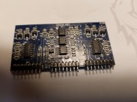
Okay I managed to burn up a 12 V regulator. Both U4 and U5 are L7812CV 12V regulators. Anyone know if these are paralleled together? I'm reading that they are with the meter.
Trying to wire up a low voltage +15 / -15 power supply to the rails so I can work on the output. I have a wire wrapped around one of the power transformers. One side is going to a half wave bridge. Plus out to the positive rail. Minus out to the negative rail. Other side of the winding going to speaker negative through a 12 lamp. No outputs or driver board in the amp. When I power it up it pulls current. 12 lamp glows bright. Any ideas?
Went over the amp with magnifier and bright light. No solder shorts. I'm getting -55V on both the + & - rails with no rectifiers in the amp. Any ideas.
I put one rectifier in and have + & - 190V. I guess it won't work with the low voltage winding. I replaced both driver chips on the driver board. Guess I'll put it in and see what I have.
Are you sure that you had the ground for the low-voltage windings on a ground?
With 55v. the bulb would have burned out.
With 55v. the bulb would have burned out.
I didn't leave the low voltage hooked up. Every time I tried it the bulb would glow bright. I tried each + & - individually and the bulb glowed bright. When I tested without the low voltage and no rectifiers I read -55v on both rails. I put one rectifier in and got + & - 190V on the rails.
Does this amp have the secondaries in series?
Does it have one pair of rectifiers per transformer?
Does it have one pair of rectifiers per transformer?
"Does this amp have the secondaries in series?"
Sorry Perry. Don't understand this question. Each secondary of the power transformer drives two of the rectifiers. The secondary of the transformer is the same as speaker negative.
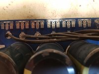
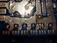
The rectifiers +&- are paralleled. Paralleled in the configuration of the pic. With no rectifiers in, I read -55V on both rails. I put one rectifier in and I read +190V on the positive rail and -190V on the negative rail. I assume this is the correct rail voltages. The rectifier in the pic is not installed. Just in the pic so you can see what kind of rectifier is being used.
Sorry Perry. Don't understand this question. Each secondary of the power transformer drives two of the rectifiers. The secondary of the transformer is the same as speaker negative.
The rectifiers +&- are paralleled. Paralleled in the configuration of the pic. With no rectifiers in, I read -55V on both rails. I put one rectifier in and I read +190V on the positive rail and -190V on the negative rail. I assume this is the correct rail voltages. The rectifier in the pic is not installed. Just in the pic so you can see what kind of rectifier is being used.
Attachments
Last edited:
Since these appear to be in parallel, you don't have to be concerned about series-connected secondaries but if you have the tutorial, re-read item 39 on the PS Troubleshooting page.
If you can't use the LV supply, at least make sure that the mute delay is working before installing the output FETs.
When you have -55 on the rails, do you also have that on the negative speaker terminal and the RCA shields?
If you can't use the LV supply, at least make sure that the mute delay is working before installing the output FETs.
When you have -55 on the rails, do you also have that on the negative speaker terminal and the RCA shields?
- Home
- General Interest
- Car Audio
- Ampere Audio 8.0