Hello
I'm servicing an Ampeg Reverberocket II guitar amp.
Here's the schematic:

I've already done the following:
Add a three prong cable, replaced all the electrolytics, changed drifted resistors, new tubes in the pre and matched pair in the final stage.
The amp delivers a noticeable hum that changes with volume pot turning.
It's not a buzz, it's more like a bass note.
I've scoped out the noise across the speaker with 5 ms/div and 50 mv/div
Volume: Max
Treble: 0
Bass: Max
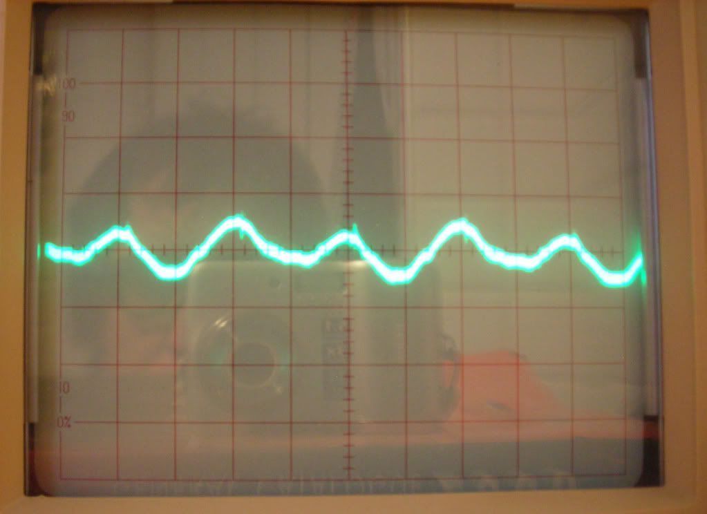
Though I'm new to the use of O-scope this appear to me like a 50Hz (I'm in Europe) noise. It's about 70 mV P-P.
The ground scheme is a sort of "buss ground" with the only connection to the chassis at ground lug of the input jack.
The first input has a ground switch (that is working properly) the other one has no switch at all.
I've tried almost everything, tube swapping, checked all ground connections, tried the "Chinese stick trick"...nothing the hum is still there.
I'm running out of ideas now.
Does anyone has a suggestion?
I'm servicing an Ampeg Reverberocket II guitar amp.
Here's the schematic:
I've already done the following:
Add a three prong cable, replaced all the electrolytics, changed drifted resistors, new tubes in the pre and matched pair in the final stage.
The amp delivers a noticeable hum that changes with volume pot turning.
It's not a buzz, it's more like a bass note.
I've scoped out the noise across the speaker with 5 ms/div and 50 mv/div
Volume: Max
Treble: 0
Bass: Max
Though I'm new to the use of O-scope this appear to me like a 50Hz (I'm in Europe) noise. It's about 70 mV P-P.
The ground scheme is a sort of "buss ground" with the only connection to the chassis at ground lug of the input jack.
The first input has a ground switch (that is working properly) the other one has no switch at all.
I've tried almost everything, tube swapping, checked all ground connections, tried the "Chinese stick trick"...nothing the hum is still there.
I'm running out of ideas now.
Does anyone has a suggestion?
If you already replaced the filter capacitors, then I would suspect one of the pre-amp tubes having a heater to cathode short. This will give you a hum that gets louder as you raise the volume; especially if it is the first, input tube. Do you have any extra tubes? Start switching them out to find the guilty one.
Daniel
Daniel
Thank you Daniel, I've already tried swapping the tubes with known good ones and move them in their socket to see if something would happen with no results.
In the previous post I forgot to mention that all the audio connections are made through shielded cables. The shield is grounded at one end only of course.
In the previous post I forgot to mention that all the audio connections are made through shielded cables. The shield is grounded at one end only of course.
I have not seen this particular amp, but I silenced some Ampeg SVTs that had ground wire soldered in the wrong place, from power supply to preamp section. As I concluded, they were manufactured with such a wiring error. May be something similar here.
Hello Wavebourn
Grounds connections is what I'm suspecting of.
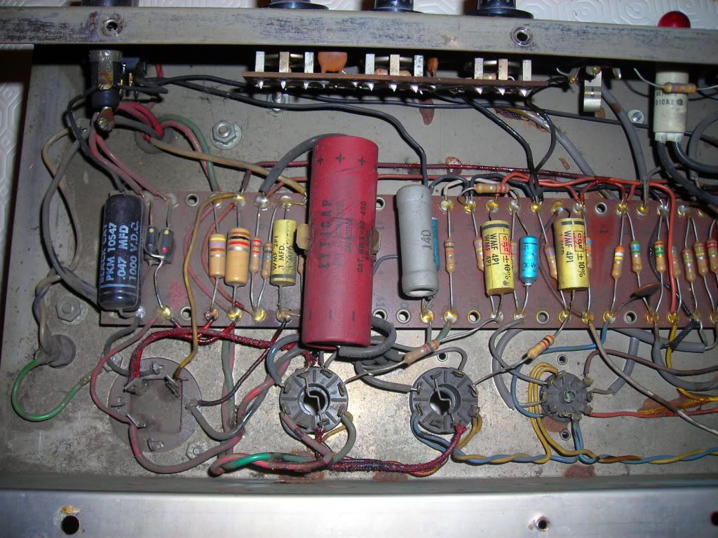
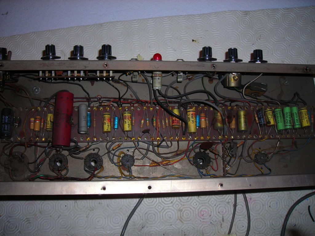
Here are two pictures of the chassis before the cap job.
Grounds connections is what I'm suspecting of.
Here are two pictures of the chassis before the cap job.
Did you solder electrolytics to exactly the same places?
Check if ground goes from transformer/rectifier by the single pair of wires directly to the filter cap, and nothing more goes through this wires. Also, some VR tube is drawn on the schematic diagram. Does it glow?
Check if ground goes from transformer/rectifier by the single pair of wires directly to the filter cap, and nothing more goes through this wires. Also, some VR tube is drawn on the schematic diagram. Does it glow?
It may be a neon power indicator rather than a VR tube. Hard to tell. The schematic isn't too clear.
Ah, never mind. It is only a pilot signal lamp. I downloaded and resized the picture. The only purpose it has other wire is to short it by power switch.
Yes, that's the pilot light.
The main switch acts as a current bleeder when in the off position.
I didn't find the exact replacement for the multi-cap can, so I've used a JJ multicap 50-20-20-20 uF.
I've put in parallel the 50 + 20 for the main cap and 20 + 20 for the second.
Then I added two 47uF on the board for the 3rd and 4th filter.
However I didn't change the ground layout.
As you can see from the picture the bridge ground, voltage divider ground for DC elevation of the filaments and the minus side of the OT are on the same ground point (on the multicap can).
Than all the grounds are daisy chained to the power tubes cathode resistor and then a single wire run to the ground lug of the input jack.
This appear to be the stock wiring as I saw pictures from another amp of the same model on the net.
A first question, two 47 uF on the board: how they are connected?
Second, how long are new wires? Can you post some pictures?
And the third question, is an input jack isolated from ground?
Second, how long are new wires? Can you post some pictures?
And the third question, is an input jack isolated from ground?
No, the two jacks are directly mounted on the chassis.
I will post some pictures of the board ASAP.
I will post some pictures of the board ASAP.
No, the two jacks are directly mounted on the chassis.
It is ground loop that may result in hum and HF oscillations.
I've unbolt the second input jack from the chassis and connected the ground lug to the first input ground. The Hum and HF noise are still there.
If I short the second input to ground the HF noise lower down a bit, but not in a significant manner.
I've tried to put a a 47nF cap across the plate and grid of the first stage.
This roll off the HF noise, the bass note hum remains and this, however, reduced the output volume too much.
If I pull out V1 the hum remains but that "pshhhhhhh" HF noise goes away.
Last edited:
first off, see if installing the grounded power cord caused a ground loop: lift the AC mains earth ground. If you or your customer is complaining about getting shocked, replace the transformer; these do not need to be earth grounded. and in alot of cases, causes issues with some pedal setups which in america you'll see some amps with the third prong removed .
ok, this I think your fighting the heater radiation, change the AC Gounding cap coming off the heater's secondary center tap.
also check the referencing resistors off the heater tap for open ground/b+ connection.
1uf poly cap with a .1uf in parallel is one of my mods there.
also check the referencing resistors off the heater tap for open ground/b+ connection.
1uf poly cap with a .1uf in parallel is one of my mods there.
Last edited:
- Status
- Not open for further replies.
- Home
- Live Sound
- Instruments and Amps
- Ampeg Reverberocket II Hum