Hello
My Ampeg BA-110 started to produce a low pitched hum, not very loud, but annoying.
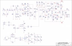
I've measured 450mV DC at the output without load and the input grounded through the return jack socket.
The DC offset seems pretty high to me.
I've also measured 0V across R213 and R214 which are rispectively at the emitter and at the collector of the power transistor.
These transistors seems to be turned off and shouldn't be negative the voltage at Q206 emitter?
Since I'm more into tubes and I'm not that good with transistors amps I need some help to end the trouble shooting.
My Ampeg BA-110 started to produce a low pitched hum, not very loud, but annoying.
I've measured 450mV DC at the output without load and the input grounded through the return jack socket.
The DC offset seems pretty high to me.
I've also measured 0V across R213 and R214 which are rispectively at the emitter and at the collector of the power transistor.
These transistors seems to be turned off and shouldn't be negative the voltage at Q206 emitter?
Since I'm more into tubes and I'm not that good with transistors amps I need some help to end the trouble shooting.
Attachments
Do you still have that DC offset with an 8 ohm dummy load attached?
Based on the numbers you've marked up (and if my maths is any good) you have 8x the current running through the feedback side of the mirror (Q202 1.7mA) vs the input side (Q201 0.2mA). That indicates a mis-match if both bases are at 0V
Based on the numbers you've marked up (and if my maths is any good) you have 8x the current running through the feedback side of the mirror (Q202 1.7mA) vs the input side (Q201 0.2mA). That indicates a mis-match if both bases are at 0V
Last edited:
Hello
Thank you very much for your reply.
Yes, the 450mV DC offset is still present with an 8 ohm load.
Since your math is surely better than mine, can you explain me, even only for educational purposes, how you did those calculations?
As I stated in the first post I'm not good with transistors, I'm trying to solve the problem in an empirycal way.
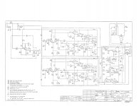
I've found a Fender solid state power amp schematic from the 70's (see the attachment), the voltages around the differential amplifier seems quite close to the one of mine. I'm quite puzzled!😕
Thank you very much for your reply.
Yes, the 450mV DC offset is still present with an 8 ohm load.
Since your math is surely better than mine, can you explain me, even only for educational purposes, how you did those calculations?
As I stated in the first post I'm not good with transistors, I'm trying to solve the problem in an empirycal way.
I've found a Fender solid state power amp schematic from the 70's (see the attachment), the voltages around the differential amplifier seems quite close to the one of mine. I'm quite puzzled!😕
Attachments
Last edited:
Link 1 & 3 of Q204. The voltage across R213 & R213 must return to zero. If it does and the amplifier stops overheating, which it will with Q207 turned on delivering 1Amp through R213 and cooking Q207!
Thank you.
Now everything is more clear.
So, which is in your opinion the culprit of this malfunction?
I would suspect Q204 since is the bias transistor, but I've tested it out of the circuit with a "ATLAS DCA Pro" analyzer (as I did with the other transistors) and it tested good.
Now everything is more clear.
So, which is in your opinion the culprit of this malfunction?
I would suspect Q204 since is the bias transistor, but I've tested it out of the circuit with a "ATLAS DCA Pro" analyzer (as I did with the other transistors) and it tested good.
The voltage across R203 and R204 tell you the currents through them and thus the currents through each of the transistors. But I missed the current through the base of Q203 🙂😛alm:🙂Since your math is surely better than mine, can you explain me, even only for educational purposes, how you did those calculations?
You just need to walk around the circuit fiinding things you can determine and work from there. It's a bit like suduko
Last edited:
- Status
- Not open for further replies.