R20 on schematic is 47.5K, BOM has it a 48.1K
Alex
:>)
R20 should be 47.5K, it set output voltage of LP38798 to 5V with R21
There's also a gap on C16, use 330uF rather than 33uF on schematic
Got everything on the Newark/Farnell site except the R16 805 1.58M thin film resistor.
They dont have a 1.58M ohm listed?
The closest in an 805 is a 1.2M
Mouser has a 1.5 and a 1.6M thin film, but the only 1.58 i see anywhere is a thick film one?
Think thats ok?
Alex
They dont have a 1.58M ohm listed?
The closest in an 805 is a 1.2M
Mouser has a 1.5 and a 1.6M thin film, but the only 1.58 i see anywhere is a thick film one?
Think thats ok?
Alex
Thanks for the info above...I actually selected the 18 ohm you referenced!
I was going to bounce all the values on the schematic with the parts BO<. would have caught the 33 vs 330 uf. Did you go thru the entire list?
If not I can here?
Alex
I was going to bounce all the values on the schematic with the parts BO<. would have caught the 33 vs 330 uf. Did you go thru the entire list?
If not I can here?
Alex
Got everything on the Newark/Farnell site except the R16 805 1.58M thin film resistor.
They dont have a 1.58M ohm listed?
The closest in an 805 is a 1.2M
Mouser has a 1.5 and a 1.6M thin film, but the only 1.58 i see anywhere is a thick film one?
Think thats ok?
Alex
As this is a low noise regulator, it's better to use quiet resistors : not thick film ones.
You can use R15=68K and R16=215K, this give Vout = -1,22*(1+R16/R15)=-5,07V
Thanks for the info above...I actually selected the 18 ohm you referenced!
I was going to bounce all the values on the schematic with the parts BO<. would have caught the 33 vs 330 uf. Did you go thru the entire list?
If not I can here?
Alex
18 Ohms is OK.
I've been quickly through the list, but I'll do a more detailed review this evening. Some caps and resistors have been adjusted during tests, this is the cause of the discrepancy between BOM and schematics.
Chris
Thanks Chris,
I know its a pain but when its done it will make things easier fro other DIY'ers.
I will wait to order parts until you do your review. I don't want to order more than once if at all possible etc or find out I am missing a part or incorrect part..thats just my "anal retentive "self...lol 🙂
Thanks for the info on the thin film for lower noise and I will try the R16 and R15 info you posted.
Alex
Ok, I finally completed the BOM pricing at Farnell, its $91 + $20 shipping for UK stocked parts. I got the solder paste, flux, and am looking to order the parts April 1 as well as a hot air gun. After looking at all those youtube videos I think this will be the way to go...or at least for now!! I will practice with the smd caps, and resistors to get the temps right.
I looked at the temp profile for the chipquik solder paste and will use this as a guide to setting the air gun temp.
Looking forward to trying this new soldering stuff out!
Alex
I looked at the temp profile for the chipquik solder paste and will use this as a guide to setting the air gun temp.
Looking forward to trying this new soldering stuff out!
Alex
There're still some pcbs left
OK, if Alex is building one I'm in. 😀 About time I learned how to use this hot air soldering station that has been sitting here for months. I still need to solder up Sergey888's Crocodile and xrk971's CMOY too. Maybe I can just have an amp-building weekend one of these days.
The only thing I've been able to listen to johnc124's handiwork (OPA1622) with so far is the eval board (sounded great!) due to the soldering issue.
As I always say, one can never have too many headphone amplifiers! 😎
I'll send a PM.
Last edited:
AGDR!!
Great, lets burn up some chips together!!! Ha!!
I will order parts on the first of April, "no foolin!!" lol
Also will order the hot air station:
2 in 1 Soldering Rework Stations SMD Hot Air & Iron Desoldering Welder ESD 862D+ | eBay
Alex
Great, lets burn up some chips together!!! Ha!!
I will order parts on the first of April, "no foolin!!" lol
Also will order the hot air station:
2 in 1 Soldering Rework Stations SMD Hot Air & Iron Desoldering Welder ESD 862D+ | eBay
Alex
I soldered my OPA1622s using a cheap polyimide stencil from OSH Stencils, solder paste, and a hot plate from Kmart. I put the PCBs on a piece of aluminum bar stock like this and then put the aluminum bar on the hot plate. This makes it easy to move the PCB to and from the hotplate without disturbing the ICs and the solder.
Hi Mark, thanks for this information.
To do the stencil I assume we need a file for the pcb from AIM65?
Then send to OSH etc...
Alex
To do the stencil I assume we need a file for the pcb from AIM65?
Then send to OSH etc...
Alex
Those small QFNs are easily soldered without stencil. It may help but it is not mandatory. Just be moderate with a solder paste, especially on the termal pad.
Last edited:
Hey Sergey!
There are several methods to solder these qfn's from what I have read, videos etc:
1. tin the existing pads and thermal pad, lay chip down, carefully use hot air gun or solder via back side of pcb if there is a via that allows for this.
2. Use solder paste, stick qfn in this paste carefully, use hot air gun.
3. Use solder paste, stick qfn in this paste and put in oven or skillet and let the heat do the trick, poor mans reflow method.
Tempted to pre-tin pads and use flux, place chip accurately, then use hot air gun to activate solder paste. The other method is just use solder paste, which has flux in it, place chip and hot air gun...
My simple mind looks at these very tiny pads and worries about bridging, but I guess if you don't use a ton of paste this should not be an issue.
Alex
Note:It seems that pre-heating the pcb is desired as well...??
Last edited:
You are not going to get bridging under a QFN IC with a solder paste, even if you use an insane amount of it. Everything from outside can be easily cleaned with a braid. Just don't put too much of it on the thermal pad. Otherwise chip will just float, potentially not even touching with peripheral pads.
The second option is the way to go.
The second option is the way to go.
I got bridging under the OPA1622 with solderpaste. TI's datasheet calls it a "VSON" -- Very Small Outline, No-lead package. They don't call it a "QFN".You are not going to get bridging under a QFN IC with a solder paste, even if you use an insane amount of it.
For me the trick was to reduce the solder paste coverage percentage on the thermal pad. <= 50% yielded success. More than that: pin to pin shorts.
To make a stencil I just sent the KiCad Paste layer to OSH Park. It was easy.
Stencils: don't do this
So here is a mistake not to make regarding stencils. 😛
Last summer I had laid out a OPA1622 adapter board, since abandoned, to use on V1.0 of the Super CMOY. I was going to wrap the OPA1688 around it as a plug-in option. I had the PC boards fabricated at pcbway.com where I've had a bunch of other boards fabbed.
I wanted to try a stencil but knew nothing about them. I noticed that pcbway had a "add stencil" option, so I figured why not. Lets see what these things are. $20 for the stencil, plus $8 more in shipping which seemed a bit odd given how small the OPA1622 chip is.
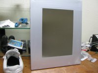
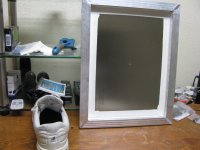
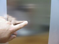
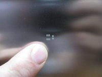
Below is what arrived. 😀 The shoe is there for size comparison. 18.5 inch x 14.5 inch (47 cm x 37cm) on a beefy aluminum frame. 😱 And yes, there are in fact OPA1622 holes right in the middle, as the 4th photo shows, at the tip of my finger.
A real conversation piece to hang on the wall! I'm guessing this fits in an industrial soldering machine somehow. I kept it thinking maybe someday I can cut the little OPA1622 part in the center out and make use of it.
So here is a mistake not to make regarding stencils. 😛
Last summer I had laid out a OPA1622 adapter board, since abandoned, to use on V1.0 of the Super CMOY. I was going to wrap the OPA1688 around it as a plug-in option. I had the PC boards fabricated at pcbway.com where I've had a bunch of other boards fabbed.
I wanted to try a stencil but knew nothing about them. I noticed that pcbway had a "add stencil" option, so I figured why not. Lets see what these things are. $20 for the stencil, plus $8 more in shipping which seemed a bit odd given how small the OPA1622 chip is.
Below is what arrived. 😀 The shoe is there for size comparison. 18.5 inch x 14.5 inch (47 cm x 37cm) on a beefy aluminum frame. 😱 And yes, there are in fact OPA1622 holes right in the middle, as the 4th photo shows, at the tip of my finger.
A real conversation piece to hang on the wall! I'm guessing this fits in an industrial soldering machine somehow. I kept it thinking maybe someday I can cut the little OPA1622 part in the center out and make use of it.
Attachments
Last edited:
- Home
- Amplifiers
- Headphone Systems
- AmpCasq: an OPA1622 integrated headamp project