Ok so I got my 2nd 41hz.com kit today, this one is a bit more powerful, its AMP7.
First impressions are:
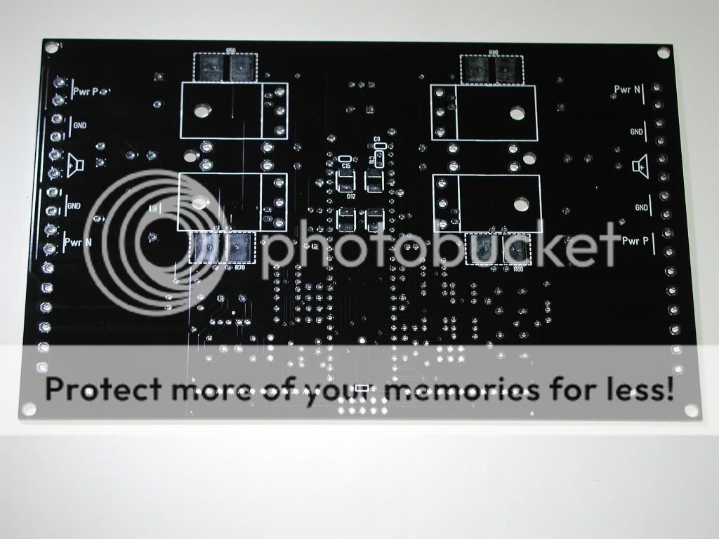
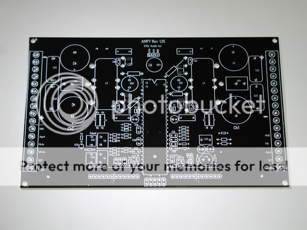
PCB is 3oz, and you can tell that by weight alone, but there are traces sticking out of the board, really love tick traces... also PCB is black, looks just awsome!
Before I got kit, I was looking at schematic and all I could find about it, and I saw that this board, amp itself is no joke. It has just about everything on it one could want. Want to bridge it? No problem, all it take is ONE jumper on connector south of IC. PCB has many connections for power in and out, signal and other important connections. It should even be able to parallel its outputs, and if so, this means this could be 1R amp!
Now that i've got the kit, which came in 2 days(Monday morning, was orderd and payed, and this morning, on Wednesday it was already here(best service ever, thanks!))
Looking inside of really nicely packed package, there were components and PCB. After looking a bit over them I found out, this is nothing like AMP2, not saying AMP2 is bad in any way, but this one is a step further on! Not only component and PCB were in it, there are spacers, washers, screws and what was best here, ceramic insulators for fets, which I had to order for AMP2 myself[ ]... So just about anything you need to finish the amp inside casing. WOOW!
There are no assembly instructions yet, but its not all that bad, it will just take a bit longer, to check everything 3 times
More to come,
Luka
First impressions are:
PCB is 3oz, and you can tell that by weight alone, but there are traces sticking out of the board, really love tick traces... also PCB is black, looks just awsome!
Before I got kit, I was looking at schematic and all I could find about it, and I saw that this board, amp itself is no joke. It has just about everything on it one could want. Want to bridge it? No problem, all it take is ONE jumper on connector south of IC. PCB has many connections for power in and out, signal and other important connections. It should even be able to parallel its outputs, and if so, this means this could be 1R amp!
Now that i've got the kit, which came in 2 days(Monday morning, was orderd and payed, and this morning, on Wednesday it was already here(best service ever, thanks!))
Looking inside of really nicely packed package, there were components and PCB. After looking a bit over them I found out, this is nothing like AMP2, not saying AMP2 is bad in any way, but this one is a step further on! Not only component and PCB were in it, there are spacers, washers, screws and what was best here, ceramic insulators for fets, which I had to order for AMP2 myself[
]... So just about anything you need to finish the amp inside casing. WOOW!There are no assembly instructions yet, but its not all that bad, it will just take a bit longer, to check everything 3 times
More to come,
Luka
Hey, sorry I didn't post nothing
I still have to take photo of finished amp, and sadly I don't have none from in between, it is hard to stop putting components on
Anyway if there is something you would like to know, just ask..
Btw, amp is already working, first day I did all settings resistors and caps, 2nd day power components, like fets, toroids[where I love the wire that was in kit, all it took is heat to remove insulation... just used solder... so simple]
Let me tell you, there are so many connections to the board, you have 4x for every connection, 4x Vpp, 4x Vnn, 4x gnd, 2x 2x speaker out, and same goes for its ground. And I set and tested both channels, even bridge, which takes only one jumper on connector, and its done!
Sound seems to be the same, better yet, better then on amp2, A HELL OF A LOT OF speaker contron, tight kick bass... I had 8R speaker, 200w, and it wanted to just out of the basket
Hey
I used
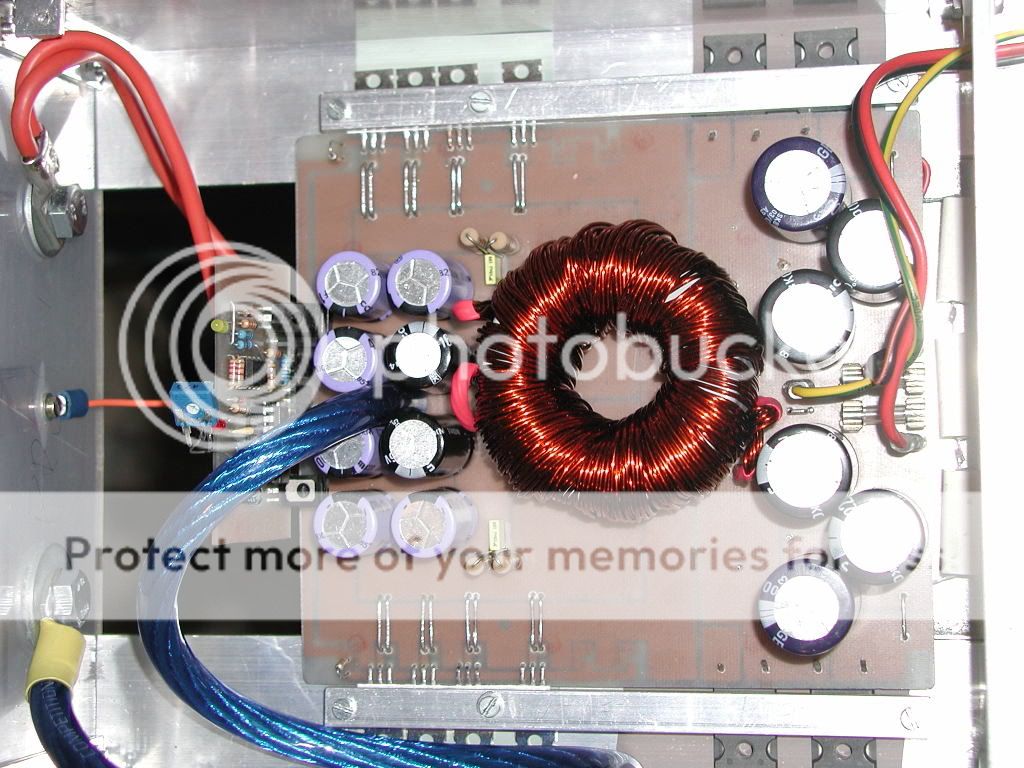
Gives +/-57Vdc at 13v input. Has a lot of capacitance on board. Funny thing is, this was still power only from 13v@10A current limited supply, but I made supply pretty damn good
As for the amp, no heatsink for test, got only warm at best
Will be something like 5mm or so tick AL plate, that will carry on this amp, amp2 and supply, that about it for heatsink. I can tell you that IRFP4321 is several times better then AMP2 stock, stw34n20[I think this is what were they]. So to anybody that will make Cladd D amp, use only good fets, heat is way lower among other even more important things
SQ is never improved in bridge, since output resistance is double, but I could say it stays the same coz you can use twice the impedance. In any case, sound comming from any tripath[I've heared bigger ones, tk2350,ta3020 and ta105a] is...well is like
I used
Gives +/-57Vdc at 13v input. Has a lot of capacitance on board. Funny thing is, this was still power only from 13v@10A current limited supply, but I made supply pretty damn good
As for the amp, no heatsink for test, got only warm at best
Will be something like 5mm or so tick AL plate, that will carry on this amp, amp2 and supply, that about it for heatsink. I can tell you that IRFP4321 is several times better then AMP2 stock, stw34n20[I think this is what were they]. So to anybody that will make Cladd D amp, use only good fets, heat is way lower among other even more important things
SQ is never improved in bridge, since output resistance is double, but I could say it stays the same coz you can use twice the impedance. In any case, sound comming from any tripath[I've heared bigger ones, tk2350,ta3020 and ta105a] is...well is like
Luka,
Nice work.
Have you compared smps to linear power supply in terms of sound ?
In assemblying amp7, do you need separate power supply for 5V and 10V dc ?
Can you upload a high resolution picture of a fully stuffed amp 7 ?
The picture will give me more confidence to assemble the amp !
Many thanks for sharing
kp93300
Hey
No I didn't use it on normal trafo, but sound shouldn't be any difrent. In any case, I don't even want to try using 2 trafos (each is +/-30Vdc) and 20000uF for each rail, I can get away with my smps with 6600uF per rail and way smaller size...I will stick to smps's
Yes you need 2 voltages, I added 2 more secondarys on my trafo, one that makes about 8-12vDc, for onboard 5v regulator, and external 10v stabilizator. Again this 2 are independent from each other
But be carefull, there are lot of mistakes in BOM, so don't just solder components in!
Picture is comming up..
I have a few similar projects on the go, for instance an SMPS board in the make that will be very universal. Also from 12V to any wanted higher voltage... I have a proto that reaches 94% efficiency, which I render rather spectacular because several commercial specimen I have in the drawer don't even reach 90%! Once it is ready I have professionally made boards that will fit TO220 and TO247 fets, it will have a separate PWM module board, you name it!... It is just plain brutal!
I have had the proto feed AMP15, AMP7 and a Truepath and in my car it sounds rather spectacular!
Oh man, I can't wait to see your pictures!
I have had the proto feed AMP15, AMP7 and a Truepath and in my car it sounds rather spectacular!
Oh man, I can't wait to see your pictures!
Cool, nice to hear that from someone else too, I know they are bad *** already at home on 10A limited supplyin my car it sounds rather spectacular!
Oh man, I can't wait to see your pictures!
You got this project of yours, some where I could take a look at it?
I have a thread at 41hz.com of the start, but I have gone through quite some development since. In the thread the SMPS converters are all still commercial designs...
Car AMP7, AMP15 and Truepath
Car AMP7, AMP15 and Truepath
I think I will have to seperate smps from amps too, farady cage..., won't know for sure if any noise will still come from smps, until I put all power and signal cables in, so far, only main voltage lines are done, everything else, 3 other voltages are via wires, real RF nightmare
Well, so far I have had no bad experiences with RF. The AMP15 has the SMPS and AMP board facing each other and it never distorted any reception of my head unit or cellphone or other equipment. I didn't even take drastic measures to minimize it. basically I wanted to see how it went without too much precautions in the first place. The SMPS are all running at between 30Khz and 35Khz...
my is now pretty low, like 20-25k if I remember right, I don't think I would need more, since I have pretty big core... anyway, I hope there won't be any noise in speakers, but until I get it semi done, I guess I can't expect too much, amps on their own are silent as they can get, that is for sure
Cool!
About the frequency, did you measure the current with just the primary connected and turned the frequency? This is a part of how I determine the usability of an unknown core. Just apply four, five or six dual windings, then connect and turn the frequency up and down, place a scope on the outputs of the chip to monitor the frequency. When the lowest idle current is reached and still very high (like 50Khz or more) then you may need more turns. When it is under 30Khz you may take some primary turns off. I always measure the inductance at 10 windings first of an unknown core, so I have an idea about the permeability and can do some rough calculations where the ideal frequency is at.
Maybe there are easier ways, I just enjoy the experimenting. It's also quite educative!
About the frequency, did you measure the current with just the primary connected and turned the frequency? This is a part of how I determine the usability of an unknown core. Just apply four, five or six dual windings, then connect and turn the frequency up and down, place a scope on the outputs of the chip to monitor the frequency. When the lowest idle current is reached and still very high (like 50Khz or more) then you may need more turns. When it is under 30Khz you may take some primary turns off. I always measure the inductance at 10 windings first of an unknown core, so I have an idea about the permeability and can do some rough calculations where the ideal frequency is at.
Maybe there are easier ways, I just enjoy the experimenting.
It's also quite educative!- Status
- This old topic is closed. If you want to reopen this topic, contact a moderator using the "Report Post" button.
- Home
- Amplifiers
- Class D
- AMP7 start to finish