 confused: hi there, i want some help. Any body please tell what would be the problem the amp I made. I notice the speaker seems like breathing, moving back and forth in very slow frequency, maybe 0.5 - 1 cycle per second. Can this be called as low frequency oscillation? The sound reproduced is quite good (base on my senses only), no signs of overheating what bothers me is the thing i mentioned aboved. The topology is quasi-complementary bridge amplifier using cheap transistors 2n3055.The input is a simple ce amp with phase splitter and phase inverter to drive its partner amp, followed by two voltage amp then next are the drivers for the final amp which operate in bridge classB. I need some help not only solved this problem but also to gain knowledge.
Yes, Low frequency oscillation or instability. It is common when you have multiple stages sharing a power supply that has high impedance. Basically it's positive feedback on/through the power supply rail, at frequencies that the filtering cap becomes in-effective. Post a schematic and we can help.
thunder amp
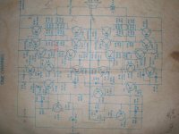
thats a "thunder power amp" very popular in phils. ,a bridged amp
having a single supply (0-50V).
the circuit claims 500-1Kw having only 8 primitive trannies (2n3055)..i wonder hows that possible!!! obviously overrated!
this circuit should not be published..
very unstable..vas is tip35a,phase splitter is c945...high THD & no zobel net.
thats a "thunder power amp" very popular in phils. ,a bridged amp
having a single supply (0-50V).
the circuit claims 500-1Kw having only 8 primitive trannies (2n3055)..i wonder hows that possible!!!
obviously overrated!this circuit should not be published..
very unstable..vas is tip35a,phase splitter is c945...high THD & no zobel net.
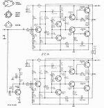
Using BC556 into the input, BD139 as VAS
BD139 and BD140 as drivers and using any power NPN to substitute the 2N3055 (as modern ones have better specifications) you will be happy.
This thing works!
here is he upper half amplifier, it is bridged.... the lower amplifier i will attach schematic has a phase inverter into the input.
regards,
Carlos
Attachments
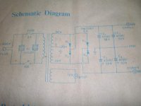
This schematic was published by Phillips do Brasil
Into 1970.
Here is, attached, better image of the lower half.
This one works!.... if you like bridge ones, using those standard transistors, old style of amplifiers, this will fit your needs.
regards,
Carlos
Into 1970.
Here is, attached, better image of the lower half.
This one works!.... if you like bridge ones, using those standard transistors, old style of amplifiers, this will fit your needs.
regards,
Carlos
Attachments
thanks for the diagrams. i want to know also how did this came out. what are the tings to avoid in the design or what must be the probable cause why this amp acting like this. any body here could give some technical stuff? as an amateur i cannot find the difference between those circuits. May the problem can be solved by this circuits but the puzzle is still there.
a correction for the vas,its a tip30a..
add a zobel net.
thats a .1uf & 10r in series
connect it to each speaker output from (+) & (-), before the fuse & inductor to 0v(gnd).
w/o input signal, carefully adjust the trimmers setting the dc offset on the speaker to zero (less than +/- 50 mV ; much better if less than +/- 10 mV).
add a zobel net.
thats a .1uf & 10r in series
connect it to each speaker output from (+) & (-), before the fuse & inductor to 0v(gnd).
w/o input signal, carefully adjust the trimmers setting the dc offset on the speaker to zero (less than +/- 50 mV ; much better if less than +/- 10 mV).
Stability problems can arise in applications in which an amplifier must drive a reactive load. Most amplifiers can easily drive purely resistive loads with no stability problems. However, some reactive loads can cause an otherwise stable amplifier to ring severely or oscillate. A good example is an audio-power amplifier. The device’s load is a loudspeaker, which presents a reactive load consisting of an inductance and a series resistance. Because of the inductor, this load appears as an open circuit at high frequencies. The addition of a simple Zobel network can eliminate amplifier instability.
i think the zobel network is used to suppressed high frequency oscillation and the high peaks of high frequency signals. isn't it? another thing i'd noticed this amp is that it's offset voltage is unstable, it fluctuates from negative to positive value. and also i found out that it was severe when the input is connected to a volume control and when i made the input open the, oscillation disappear.
now im wondering your pcb layout & grounding -bus or star?..as i have said before the circuit is very unstable.
have you ever tried experimenting an amp w/ & w/o a zobel net?
i have done it before w/o the net. & i do have LF oscillations.
the circuit should undergo a "major operation"
well i could modify the "thunder amp" but its not for free.
have you ever tried experimenting an amp w/ & w/o a zobel net?
i have done it before w/o the net. & i do have LF oscillations.
the circuit should undergo a "major operation"
well i could modify the "thunder amp" but its not for free.
I'm more of a tube guy, but I'll take a crack at it anyways.
About the power supply, it shows separate rectification for each channel. Make sure you are NOT using separate rectification for each half of a single channel. Nor should there be any significant amount of resistance in the power supply or ground conductors between the two halves of one channel. Any difference in power supply voltage between the two halves will show up at the output.
It appears on the audio schematic that you switch the collector-emitter on some of the transistors. Did you switch them in reality or are those just meaningless scribbles? The original print looks to be the correct wiring.
Things to try:
Test each half by itself- Use two separate coupling caps to block DC and two separate loads. Check to see if the sound coming out of each section is ok. Also, check for sub-sonic oscillations. You will either have to use a capacitor- load combo that is capable of passing really low frequencies. Or use an oscilloscope before the coupling cap to check. Also try adjusting the bias pot to several places and make sure the DC voltage at the amps ouput always equals V+/2. If it varies when you adjust it, then you may have to tweak some things possibly resistor values in the Sziklai pair.
- Status
- This old topic is closed. If you want to reopen this topic, contact a moderator using the "Report Post" button.