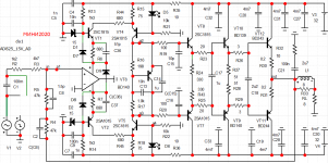
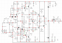
Did somebody infact observe the funny wiring of R14/R15 in the original cckt diagram? (Unless these are actually fuseable resistors) It would make more sense to move these in the emitter section of both output transistors. Then you could simply design-in a overcurrent protection circuit; connected either directly to bases of output trannies - or to R9 and R8.
Did somebody infact observe the funny wiring of R14/R15 in the original cckt diagram? (Unless these are actually fuseable resistors) It would make more sense to move these in the emitter section of both output transistors. Then you could simply design-in a overcurrent protection circuit; connected either directly to bases of output trannies - or to R9 and R8.
It is more reliable and easier to close transistors T1 and T2 by closing them to the ground.Checked