Hi
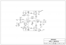
This simple amp was repaired (change the IC in one channel) at a friend of mine repair shop. It works pretty well, put out 102W on resistive 4 ohm load, clipping is perfectly simmetrical, and sounds pretty decent.
Now I intend that offset is controlled by the IC, but how the 35 mA bias (measured) is fixed?
Attachments
Complete disregard for the safe operation of the amplifier.Guaranteed burnout of the output transistors and the tl071 operational amplifier when a through current occurs
Thanks, now I can put it in Spice and see what happens. The thingy is a comercial one, tested in the lab, and seems to work just fine. Brand AudioMiller, or something, from Brazil.
What happens when BC546/BC556 breaks through ? How is the thermal stability of the quiescent current of the output transistors provided in the absence of emitter resistors? As components of the amplifier are protected from end-to-end current? Where is the output stage correction?
🙂 I´m not advocating this circuit, was just curiosity about the bias control mechanism. The unit has no other protection than the fuses, and on the heatsink only the Darlingtons.
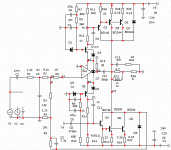
A similar amplifier was published in Radio magazine No. 1 in 1989 .Author of the publication E. Gumel. Here is an upgraded version based on the accumulated experience.Overload protection is not shown.
C8 capacity from 0.47 UF to 2-4mkf polyester or polypropylene
C8 capacity from 0.47 UF to 2-4mkf polyester or polypropylene
Attachments
With the typical 1.4mA Iq of a TL071, the drop on R8/R9 is 950mV, there is hardly any quiescent in the output (so it cannot run away). The BC... are just cascodes to eat half the rail voltage, leaving +/-18V for the opamp.
Even the max. 2.5mA will only drop 1.7V at R8/R9. The 10k will then allow 60µA base current. At this base current beta is perhaps 500, giving 30mA max bias. A typical TL071 will more likely keep the outputs off (<1mA). This is borderline class B.
In reality its own offset will make the TL071 draw just enough additional current from one rail that one of the Darlingtons conducts just a little bit to correct the offset. Still no real bias.
Where is the output stage correction?A similar amplifier was published in Radio magazine No. 1 in 1989 ...
Last edited:
nice, the double outputs is because BD244 is only 65W?
Actually, there are Russian analogues KT818G/KT819G.But the MS-12 doesn't have its own models.And they are 100 watts. You can use BD909-BD912 . When parallelizing, distortion is reduced, and the spread of transistor parameters is reduced.The amplifier operates in class B with a 2 mA quiescent current
Where is the output stage correction?
Requires C8. Eliminates the tendency to create through currents.Diodes protect in the clip
AD825 was used in modeling.
Last edited:
Hola hermano 🙂
Not surprised at the crude design.
Brazilians can and do have excellent designs, such as Gradiente, but since internal market is huge and protected from external competition, you can grab a random schematic from dubious pages, manufacture and sell it successfully.
That design has lots of problems, but since it works, sort of , let it as is.
1) as stanislav said, zero short circuit protection
2) very underrated or marginal components or straight at the destruction edge:
* TL071 is being fed half +V , so +/-19V .
Minus some 0.7V , not too much comfort on that.
Maximum design voltage is +/-18V , and in generally *nobody* uses them with more than 15/16V rails (which are perfectly safe)
To boot voltage reference is not regulated, not even decoupled (WTF?), so that´s one extra bullet in the russian roulette revolver.
* BC547/556 are small signal transistors.
They are being used within their ratings , but it scratches me the wrong way seeing them doing some kind of Vas duty in a 100W power amp.
* 10k resistors in series with power transistor base is ridiculous, voltage drop is immense and unjustified.
Typical composite Hfe is around 1000 , so when driving 100W into 4 ohm loads peak current is near 10A ... base current then would be 100mA
Now calculate voltage drop across >>10k<<<
There is also the "small detail" that 10k is practically in parallel with 680r
So feeding 100mA into it will also feed 14 times more (1.4A?) into that resistor.
Somehow I guess it´s an impossible task for a puny BC547 .
I guess it´s a typo.
* bias is fixed, random (depending on Op Amp idle current), not adjustable unless you use two , say, 1k presets instead of 680r´s and in any case it does not thermal track heatsink temperature by any means.
That it works at all may be possible because it must certainly be underbiased at idle.
Sadly, tons of such crude circuits around , which act as magnets to beginners because of their simplicity.
Last edited:
Post #15 - Elektor version - R8 R13 are very high value 1.4k , cross conduction of mosfets in high frequencies or oscillation is guaranteed . Emitter followers need to be added for proper mosfets Cgs discharging ,someone can try to simulate this .
Simple schematics has their own drawbacks ... It may sound ok , but you may not understand why heatsinks are more hot than it should be .
About darlingtons - same problem with cross conduction . They are mostly slow speed ,best suited for linear voltage regulators, internal resistors in transistor are too big for fast turn off speed . Amp may become unstable at high power or high frequencies and then both npn and pnp will be open ,thus shorting power supply and destroying themselves . So be careful . I think output stage must be able to work enough fast ,for amplifier to be stable - if output stage is slow ,it causes delay , that causes feedback to oscillate .
But darlington with 10k base resistor in series - too slow for anything ... Interesting would be to see how these amplifiers behave in simulation with square wave input .
Denon designed and marketed very successful amplifiers based on OPAMPs. Their circuit arrangement was conventional but also simple, cheap and included normal protection circuits. A snip of Denon PMA350 model power amp. schematic is attached. Compare with the Elektor type circuit (Elektor published a few versions over some years). They were similar to that posted by Apex but also had BJT output stages rather than mosfet.
PMA350
PMA350
Last edited:
- Home
- Amplifiers
- Solid State
- Amp with TL071 front end