Not sure what forum to put this in, I guess this is the closest one..
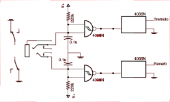
I've added a Mosfet version of the fender trem (from Geofex.com) to my 5E3 build along with a one tube reverb. Both work well and now i'm building the switching box.
I'm using a CD4093 to control a CD4066 which does the switching. attached is the schematic. The power supply comes from the 6.3V heater through a voltage multiplier to give about 9VDC. The SPST switches are in the switchbox with a TRS cable to the switched TRS jack. I used this scheme instead of just using the SPST switches to manually switch the circuits off because I was getting some ticking from the Trem since in the switchbox both the reverb and trem have to use the same ground. I built a TRS cable from canare two pair individual shielded cable, with the reverb shield grounded. I also wanted to use solid state switching so I could add LED indicators to the switchbox.
So I figured it would be as simple as adding a current limiting resistor and LED to the switch/gate input. Well, that lowered the voltage too much and pulls the gate input low no matter what. I know you can't directly power an LED from a gate output because it will pull the gate voltage low, so you need to use a transistor to control the LED. I tried using a transistor as an inverter connected to the switch, but that pulls the voltage on the inputs too low also. It seems I can't connect anything to the gate inputs or it will pull them too low.
The trouble is, using a TRS cable with this switching scheme the only things I can switch are the gates to ground. If I were using like 5 conductor XLR jacks or something then I could rig up another chip in the box to switch stuff, but I want to stick with the TRS. Any ideas of how I can add an LED indicator to this system?
Attachments
Last edited:
You should have another pair of gates in the 4093. You could wire these as an inverter and hook up the input of this inverter to the control input of the 4066. Then drive the LED cathode with the output of the inverter (LED anode connected to V+ through a series resistor).
Remember to tie all unused INPUTS of your CMOS chips to a known potential (VDD or VSS) to avoid floating gates and associated issues.
~Tom
Remember to tie all unused INPUTS of your CMOS chips to a known potential (VDD or VSS) to avoid floating gates and associated issues.
~Tom
yes, I do have two more gates but I want the LEDs on the switchbox. I guess I should have said that. If I drive them with the inverter gates then I need two more wires in the cable/jack which I don't have with a TRS.
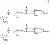
I decided to ditch the CD4093 and just actuate the 4066 directly. I used the 4066 switches similar to logic gates, and wired them in series. Now I can directly attach an LED to the switch control pin without brining it low. Here's the schem. Works great, the switch, LED and LED resistor are in the footswitch box. TRS switched jack to connect both channels and shut off the verb and trem if the pedal is not present.
Attachments
- Status
- Not open for further replies.