Seems simple enough to "build" in LTSpice - maybe it would be fun for you to see all the voltages and currents before trying to build it for real.
Those Darlingtons are cheaper as TIP142 TIP147. Darlingtons make a circuit simpler but with some compromises in the cost and speed performance, and the 5K base resistor is not ideal for linear use like an amplifier. How important is it to keep it this simple? This is a classic amplifier from about 1968. A couple years later, we added a LTP as in the "Sinclair" modules, and a VAS CCS. Then we added output protection, first current limiting and then VI protection which had issues, so we mostly went back to just current limiting. Then Douglas Self refined the art of VFA amplifiers with LTP degeneration and a ~Darlington VAS etc. All these improvements involve adding cheap signal transistors. More recently we have added 2-pole compensation and cascoding in a couple places. Other tricks include folded cascode VAS and CFA but those are different strategies. Some ideas like symmetric IPS are problematic and of little benefit so I do not recommend them. If you goal is just to fiddle with simple circuit, this is fine, but if the results matter at all, I would be a bit more ambitious.
Thanks for the info.Those Darlingtons are cheaper as TIP142 TIP147. Darlingtons make a circuit simpler but with some compromises in the cost and speed performance, and the 5K base resistor is not ideal for linear use like an amplifier. How important is it to keep it this simple? This is a classic amplifier from about 1968. A couple years later, we added a LTP as in the "Sinclair" modules, and a VAS CCS. Then we added output protection, first current limiting and then VI protection which had issues, so we mostly went back to just current limiting. Then Douglas Self refined the art of VFA amplifiers with LTP degeneration and a ~Darlington VAS etc. All these improvements involve adding cheap signal transistors. More recently we have added 2-pole compensation and cascoding in a couple places. Other tricks include folded cascode VAS and CFA but those are different strategies. Some ideas like symmetric IPS are problematic and of little benefit so I do not recommend them. If you goal is just to fiddle with simple circuit, this is fine, but if the results matter at all, I would be a bit more ambitious.
For basic, non-critical amplification purposes, say, casual use, would this design be ok?
Also, those darlingtons - with the internal resistors, what if darlingtons without resistors were used?
And would the addition of external emitter resistors as in traditional bipolar designs (0.47 ohms) be of benefit?
No Vbe multiplier might be a problem.
Will possibly either have crossover distortion or dissipate too much power in outputs.
Will possibly either have crossover distortion or dissipate too much power in outputs.
You definitely want emitter resistors if you even attempt to bias it above pure class B. To get it to bias into class AB you probably need to add a 4th diode to the bias stack, and parallel that 4th diode with a pot. Either that or stay with 3 diodes increase the series R beyond 47 ohms. Again, make it a pot. You could use a vbe multiplier, but for something this simple, diodes and a pot are fine.
Darlingtons don’t work as well as discretes because of the base-to-emitter resistors on the driver. They are undesired - period. It will work, but not as well as without them. The base to emitter resistors on the outputs themselves are needed. That direct connection isn’t as good as going across both the vbe and the emitter resistor together, but it’s better than nothing. None of the TIP or BD type darlingtons have just the Rbe on the output and not the driver. But some of the Sanken audio darlingtons just have the one Rbe on the output alone - check the data sheets. Those are good types to use if you can get them.
Just the one gain stage does work, but don’t expect miracles. Closed loop gain and input impedance are pretty low since it forms a virtual AC ground at the base. Adding the extra singleton PNP input stage is worthwhile - you don’t need or want to go to an LTP pair if you’re running off a single supply. Better loop gain and therefore distortion, and setting the DC Q point voltage at the output is less touchy.
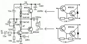
First transistor and bias string current looks around 3 to 4 mA
so with the 3 diode drops its enough to bias the Darlington's
probably barely enough just to get them going likely around 5 to 7 mA
So to get bias up to 30 to 40 mA for the darlingtons just add
one more diode.
Then likely bias would shoot up too high around 100 to 140 mA
So you could adjust the current of the bootstrap.
Which should probably stay where its at.
Or just lower the value of the 47 ohm resistor
likely a low value around 8 to 12 ohms would set the bias
right.
Basically yes just add .22 emitter resistors on the Darlington's
so bias would behave. and the bias could be checked more easily as well.
Input sensitivity wouldn't be very high
to reach full power the preamp would need a enough gain of course.
3 diodes not enough and 4 way too much. So put a 500 ohm pot in parallel with the 4th diode. That will provide a workable adjustment.
3 diodes were originally used to try to get away with no emitter resistors. The 5 to 7 mA that you see is ALL in the drivers (vbe of the outputs divided by the Rbe in the darlingtons). You COULD get away with this if the amp had more loop gain (feedback) to work with.
3 diodes were originally used to try to get away with no emitter resistors. The 5 to 7 mA that you see is ALL in the drivers (vbe of the outputs divided by the Rbe in the darlingtons). You COULD get away with this if the amp had more loop gain (feedback) to work with.

I've got several boxes of NOS NTE263/264's in stock, but also some darlingtons what don't have internal bias resistors.
I'm wondering if something like that would be better suited for this basic design.
Because I dislike the lack of "control" due to those internal resistors.
I know the first transistor's resistor is for limiting reasons.
I'm wondering if something like that would be better suited for this basic design.
Because I dislike the lack of "control" due to those internal resistors.
I know the first transistor's resistor is for limiting reasons.
The only darlingtons I’m aware of that don’t have the internal resistors are the D40-D43 types (and ECG equivalents). Dissipation and current capability of those is a bit anemic for 40 volt supply. 25 or 30 volt, maybe. Meant for amplifiers in the 5 to 10 watt range or as drivers. And since they don’t have the resistor from emitter to base on the output device switch off will be slow, which increases the cross-conduction currents at high frequency. Probably ok on such low supply rail, though.
The 263/4 are the next step above the TIP122/7, which I have used in that type amplifier and it does work. If you have them and they are free there is certainly no harm in using them. Sanken makes the kind you’re really “looking” for with only an Rbe on the output device, but they are spendy.
The 263/4 are the next step above the TIP122/7, which I have used in that type amplifier and it does work. If you have them and they are free there is certainly no harm in using them. Sanken makes the kind you’re really “looking” for with only an Rbe on the output device, but they are spendy.
I'll go through my vast stock of NTE/ECG/Toshiba/ST, etc. and see what I have in alternative transistors.
Its just a fun simple Darlington amplifier.
Audio can be fun, and this topology is simple and stable.
Be fun project for anyone. 3 transistors cant beat it.
Something to breadboard in one day and have a listen.
Basically any or most Darlingtons will have the built in resistors.
Not a big deal for the application.
T0-220 darlington package will range from 60 to 100 volts
so many are suitable.
Wattage rating will range from 40 to 85 watts,
or basically around 2 amp, 5amp, 8amp or 10 amp
Such affordable little guys, might as well shoot for a 8 or 10 amp rated Darlington.
2N6040/43 , 2N6042/45 , BDX33/34 , BDW93/94
BDW42/47 , TIP100/105, TIP 101/106 , TIP102/107
yeah I was slightly fascinated with simple Darlington amps a few years ago, LOL
Usually " general purpose" Darlington's dont even rate transition frequency
cause its usually low around .8 to 1 MHz
Think the fastest cheapos I found were BDW42/47
which are 4 MHz. Which is comical I know.
But fast for a Darlington, LOL
Aside from really expensive Sankens.
which likely would have no improvement
with such a simple single gain stage.
There is probably over 20 to 100 feasible designs.OK......
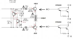
How about this "mod" or design in place of the original outputs?
Thoughts?
First design was 40 volt single supply.
New post shows 100 volt dual supply.
But in all simplicity , I think your point is adding .22 emitter resistors
so yes to that.
far as the rest, im doing very basic DC analysis of the original circuit.
just looking at the actual currents.
then looking to do very basic mods to make it all work.
basically were looking to add a 4th diode, make it bias right.
then likely typical mods for a capacitor coupled amp.
larger output cap for better bass, then the bootstrap cap is small 10u
should be typical 100u for better bass as well.
sticking with the original design with one adjustable pot.
since its single supply, the pot is adjusted to get half supply
on the output per original design.
Basic DC analysis of original circuit
Obviously I didnt use a trim pot, just set resistor
to get output at 1/2 supply voltage.
My guesses in post #7 somewhat close.
I expected Darlington bias to be around 5 to 7ma
it is as expected though, very low at 3ma
simulation is at cold start temperature 20c
I'll do some small mods

Obviously I didnt use a trim pot, just set resistor
to get output at 1/2 supply voltage.
My guesses in post #7 somewhat close.
I expected Darlington bias to be around 5 to 7ma
it is as expected though, very low at 3ma
simulation is at cold start temperature 20c
I'll do some small mods
Then I did some basic mods
Added 4th diode to bring bias up.
Increase output cap to 3800u to 4700u.
Use 100k trim pot, R5 adjusted so 1/2 voltage
should be obtained pretty close to the pot being centered/ 50%.
Added .22R emitter resistors
Increase bootstrap Cap from 10u to 100u
that is about it.
bias should be good.
if you need to lower/raise
change R2 3.3k for more 5k for less
4.7k should be about right
Forgot to mention R1 , 47R could be eliminated.
But if you include it as part of the bias string
like the original layout.
Bias would shoot up to 120 mA
its why I bypassed it.
if you wanted adjustable bias with a pot or trimmer
you could make R1 a 50 ohm trimmer. And include
it in the diode string.
Actually it doesn't need to be more than a 20 ohm trimmer
because the value needed is around 3 to 8 ohms
so even a 50 ohm trimmer would make bias jumpy.
Thanks much Dragon!
I will do a temp build on the breadboard, check volts, and report back when I get it rigged.
I'd also mught use heavier outputs like 10A versions, maybe increase B+ for more wattage too.
I will do a temp build on the breadboard, check volts, and report back when I get it rigged.
I'd also mught use heavier outputs like 10A versions, maybe increase B+ for more wattage too.
Yeah pretty much
You could use good old TIP142/147
which is much larger T0 - 247 package than T0-220
then of course 2N5961 could be changed to any number of
common higher voltage transistors. Think its only 60 volts
maybe 160 volt 2N5551 or higher current like a ZTX
or zillion others.
You could use good old TIP142/147
which is much larger T0 - 247 package than T0-220
then of course 2N5961 could be changed to any number of
common higher voltage transistors. Think its only 60 volts
maybe 160 volt 2N5551 or higher current like a ZTX
or zillion others.
- Home
- Amplifiers
- Solid State
- Amp questions