I have a newer Lanzar opti 1000d and recently it turned on with the protection circuit activated with a red light instead of a green light. I pulled the amplifier apart to find that a screw had gotten loose somehow and touched the circuit board, it touched one of chips simalar to appearence to this one (http://n1vg.net/opentracker/images/chip-large.jpg) I know this due to the mark on one of the pins. can anyone help me troubleshoot this problem and give me and idea what could have blown or what to check. any help is appreciated!
Hi androtaker56
Can you maybe post a couple of photo's of the IC that was shorted by the screw? As well as the IC number? It would be a bit easier, as I do not know what IC was shorted (Could be an OPAMP, Comparator, PWM IC, ClassD control IC, etc). For now I'd recommend looking for any obvious problems, like burnt resistors, diodes, all the usual stuff. Also do you maybe have a schematic, then I'll be able to be more specific to help solve the prob.
Regards,
Werner
Thats your PWM IC. You could always desolder it and replace it if you have decent soldering skills.
It may also be one of the other IC's that I have mentioned. I have seen alot of car amps whose protection circuit relies on more than just the PWM IC.
I have been searching for schmatics on it but no luck yet. as for the photos I will try to post them as soon as possible. but I should be able to get it on here tomorrow if I remember. ill also post the chip number.
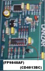
that looks like a dual-flipflop IC. here is the Datasheet
http://www.fairchildsemi.com/ds/CD/CD4013BC.pdf
It´s probably used for the protection curcuit, but it could also be used for a square wave generator to drive the mosfets. Is there no IC with the numbers 494 , 2525 or 3525 on the board ?
As you say the amp always stays in protection mode, it´s more like that the power supply (including the protection curcuits) are ok and it´s more likely that the music-power section has a fault. Check for shorts in the music section power parts.
Hi
ok, I`m not too familiar with digi-amps, but the protection curcuits basically follow the same rules as they do in analog amplifiers. "If anything goes wrong ---> disable the PWM-controller".
The PWM-controller is the TL494 , that means this IC delivers the driving signal for the SMPS-mosfets and controls everything that has to do with the SMPS.
But the protection is usually done with a couple of transistors or a Op-Amp IC. (that could be the small IC next to the 494 on your picture) , in korean amplifiers this usually is a KIA4558 - OpAmp.
Usually the protection curcuit is divided , that means there are more than one protection curcuit. E.g. one monitors the temperature, the other one is activated by a short @ the output stage of the music amplifier.
The protection curcuits usually combine their output signal , this is fed to the TL494. The TL494 has an output control pin, but in most car amplifiers this pin is always connected to the reference voltage pin (The TL494 has a precision volatge output pin that delivers 5V) , that means the TL494-outputs are always enabled. The shutdown function usually is achieved with the error-amplifiers of the TL494 .
Here you find a basic application of the TL494 . in most amplifiers the TL494 is used in the same way or close to that. There you see whenever one op-amp delivers 5V at it´s output, the TL494 is shut down and the red LED is turned on.
TL494 application ( car amp)
Try to find similarities with your amplifier. You should be able to find out where the shut-down signal comes from in your amplifier.
BTW: When you want to power up your amp on the workbench add a 2Ohm/10W resistor in series to the +12V power cable. this will prevent parts when there would something go terribly wrong 🙂 , or use a power supply that will only deliver 1-2Amps
just to make sure, you are saying that if I can find the op amp that is supplying 5 volts to the tl494 and disconnect that pin then I will have bypassed the protection. or depending how it is made I can just find the input on the tl494 that is being supplyed with the 5 volts and it will bypass both protection circuits.
its gonna take me a minute to get this simple circuit down, but ill get it, I havent used the skills I learned in class for over 3 years. it doesnt really get anymore difficult then a couple resistors and leds for aircraft wiring. and we dont take apart the electronics.
Hi
your amplifier may not using precisely the same curcuits, I suppose the curcuits are similar (now that´s a difference). Try to figure out how the TL494 is used in your amplifier. If that small IC (check the number with google) next to the TL494 is an OpAmp get the datasheet and check how the OpAmp is connected to the TL494. If that is similar to my schematic, check the curcuit lines from the OpAmp , there should be a curcuit line that goes to the music section.
And don´t bypass the protection curcuits ! Assuming the protection curcuit is working fine then there is a fault in the music section. If you bypass the protection curcuit , the SMPS will power up and in this case I bet there will be something going up in smoke.
Try to follow the curcuit lines to determine why and from where the protection curcuit is activated. If the flipflop-IC is connected to the OpAmp (or connected to the error-amplifier of the TL494) desolder that flipflop IC and take it out of the curcuit board. With the datasheet of the flipflop IC you can set up a small test curcuit for the flipflop-IC and follow the truth-table to see if the flipflop-IC is working properly.
If it is not possible to follow the curcuit lines or to determine how the protection curcuit is working I ´d suggest to start the other way round. That means checking all the power-parts in the music section for shorts . Also, you mentioned that a screw got loose inside the amp. If that screw caused a couple of shorts the rectifier-diodes may be damaged. Was that screw stuck to the IC you mentioned in your first posting or was that srew totally loose and able to touch other parts as well ?
it stuck to it and I do not believe it touched anything else. ill start working on what you suggested. there is no small ic next to the 494 the small ic is next to the ic shorted (cd4013bcn), the small ic # lf411cp (confirmed op amp). the 494 chip has a chip the same size located near it with the number lm324n, and I have followed the temp sensor through the circuits to the lm324n chip.
Hi
Hmm, things are getting warmer 🙂 The LM324 is an OpAmp IC , often used for switching purposes.
LM324 Datasheet
Steph
Hmm, things are getting warmer 🙂 The LM324 is an OpAmp IC , often used for switching purposes.
LM324 Datasheet
Steph
alright ill see tomorrow if lanzar will give up the schematics. ill keep following circuits to see if I can find them out. I have to do a little research to try to get more familiar with how the amp works as far as the internals go. like I said ive had training but remember very little about it. and it wasnt really too indepth. if you have any other ideas to walk me through this please let em fly. thanks
I am still waiting for lanzar to get back to me. I had seen on another thread on this site where a person gave the volt reading off the pins for the ic's and the person assisting could help by these readings. will it help at all posting these readings ( if the amp build is not available).
that is an zed audio built lanzar,drop them an email they may help you, zedaudio.com located in cal. usa
- Status
- Not open for further replies.
- Home
- General Interest
- Car Audio
- amp protection circuit malfuntion