
Hi,
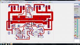
mark out the length of the trace connecting the collector of T20 to the collector of T21 via the 2 HF (0.1uF) decoupling capacitors.
This route should be 10 times shorter.
mark out the length of the trace connecting the collector of T20 to the collector of T21 via the 2 HF (0.1uF) decoupling capacitors.
This route should be 10 times shorter.
I miss base stoppers for your power BJTs.
You like to draw you schematic in a chaotic way and this is reflected by pcb design to some extend.
Connections are way too lengthy, loopy and for the power parts way too thin.
You like to draw you schematic in a chaotic way and this is reflected by pcb design to some extend.
Connections are way too lengthy, loopy and for the power parts way too thin.
Hi zeus_threat
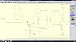
I only looked briefly at your schematic diagram and I found it to be very difficult to follow, it’s very clunky with wires flowing through components and values written on top of wires. Look at some of the other designs seen in DIY to get an idea how a schematic should be drawn.
Some traces seem to take the long way around to get to their destinations. They can be shortened considerably.
The technical issues:
Looking at the diagram it seems to be a fairly standard design; however what is the purpose of R26?
What are the supply voltages feeding your design?
What is the intended speaker load impedance?
What is the intended application; (home, pro-audio, etc) this will help define the heatsinking requirements?
Although the TIP 2935 and TIP 3055 are really cheap, there are much better output transistors available (faster, more powerful, more linear, etc).
Do you have an output filter network in your design? Because its not shown on the schematic.
If this is your first DIY amp project I would suggest that you be very careful about output overloads and short-circuits. It might be a good idea to add a V-I limiter to your design if there is any chance of a short.
I will leave it to others to simulate the design and check the component values.
As for the PCB layout:
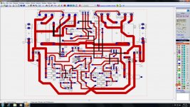
Is this a double sided layout, (traces on both sides)? With a little better (imaginative) component layout you can get rid of most (if not all) of the jumper connections on the second layer. This will greatly reduce the cost of the PCB and improve the reliability of the amp.
If you maintain the use of a double sided board, than, using a single via to conduct current is not a good idea, they tend to open. Use the component lead to carry the current from one layer to the other.
Again what is R26 doing on the board?
On your board why is the pad layout for T16 not the same as T17, and for esthetic reasons, you could orient them in the same direction.
The traces connecting D6 D7 should be the same size as the output traces. This is due to the fact that very often these diodes fail and the small trace will burn before the fuse opens.
You will need some large pads for the power connections on the PCB (hint, look at the fuses, ground, output connections, etc).
I hope these comments help, have fun with your project.
Philip
I only looked briefly at your schematic diagram and I found it to be very difficult to follow, it’s very clunky with wires flowing through components and values written on top of wires. Look at some of the other designs seen in DIY to get an idea how a schematic should be drawn.
Some traces seem to take the long way around to get to their destinations. They can be shortened considerably.
The technical issues:
Looking at the diagram it seems to be a fairly standard design; however what is the purpose of R26?
What are the supply voltages feeding your design?
What is the intended speaker load impedance?
What is the intended application; (home, pro-audio, etc) this will help define the heatsinking requirements?
Although the TIP 2935 and TIP 3055 are really cheap, there are much better output transistors available (faster, more powerful, more linear, etc).
Do you have an output filter network in your design? Because its not shown on the schematic.
If this is your first DIY amp project I would suggest that you be very careful about output overloads and short-circuits. It might be a good idea to add a V-I limiter to your design if there is any chance of a short.
I will leave it to others to simulate the design and check the component values.
As for the PCB layout:
Is this a double sided layout, (traces on both sides)? With a little better (imaginative) component layout you can get rid of most (if not all) of the jumper connections on the second layer. This will greatly reduce the cost of the PCB and improve the reliability of the amp.
If you maintain the use of a double sided board, than, using a single via to conduct current is not a good idea, they tend to open. Use the component lead to carry the current from one layer to the other.
Again what is R26 doing on the board?
On your board why is the pad layout for T16 not the same as T17, and for esthetic reasons, you could orient them in the same direction.
The traces connecting D6 D7 should be the same size as the output traces. This is due to the fact that very often these diodes fail and the small trace will burn before the fuse opens.
You will need some large pads for the power connections on the PCB (hint, look at the fuses, ground, output connections, etc).
I hope these comments help, have fun with your project.
Philip
I forgot to add that the Text silk screen on the board are not well done, you will not be able to read some of the text when the board is assembled.
Cheers
Philip
Cheers
Philip
My first post here so first my thanks to all...
i would move the protection diodes to the outside ends of the output trace,
put in a separate power ground near to the output devices and move the zobel network much closer to here also.
regards
ciaran
i would move the protection diodes to the outside ends of the output trace,
put in a separate power ground near to the output devices and move the zobel network much closer to here also.
regards
ciaran
Cleaner Schem
Hi thanks for all the comments i will get the power section layed out differently including all you have mentionned. Attached is a cleaner schematic. Amp is for home use +-35V and single driver that does not dip below 6.53 ohm in impedance measurements. TIP will be used as i have plenty of them around. The amp has been simulated and built it is now being moved to pcb.
I am getting used to target pool thats why you don't see an inductor in parallel with R26 it will be there in final circuit 1uH in value.
As for VI protection I have yet been able to find a complete calculation guide that explains how to calculate values for at least a single slope protection scheme and derating with increased temperature. If anybody has any information regarding this i would be glad if you could please pass it on thanks.
Attachments

- Status
- Not open for further replies.
- Home
- Amplifiers
- Solid State
- AMP PCB LAYOUT