Hello everyone, There are many ways to measure amps output but I need one that is cheap and simple!
I have about 4 heating elements of different ohmages, 2 more of the same ohms (2*16 --> parallel to 8 OHMS at some wicked wattage, especially when placed in water!) And some small 25W 25 ohm resistors.
What im asking is can I use the heating elements to test my amps output? Does anyone NOT recommend this? Problems? Harmonics? Inductive elements?
Its about 1kW theoretical output watts. Im hoping I can take it to 1.2kW at least!😱
Thanks GamerAndds
If they can actually dissipate that power without making smoke they are good for tests (short tests)
Also you need to know that they can mantain their impedance flat when you do your tests because they can go higher when they get hot ; or when they are cold they can cause stress in the output stage, and also when you test at different freqs (it would be good that you could also measure its inductance, if they are wired heating element (common ones) the inductance could affect if it is high )
Also you need to know that they can mantain their impedance flat when you do your tests because they can go higher when they get hot ; or when they are cold they can cause stress in the output stage, and also when you test at different freqs (it would be good that you could also measure its inductance, if they are wired heating element (common ones) the inductance could affect if it is high )
Hi,
A typical 1kW bar fire heating element draws about 4 amps for
250V and about 9amps for 115V, the latter is clearly ballpark
for testing amplifiers, two in parallel are 6.6 ohm and 2KW.
For 250V elements you can rewire sections in parallel.
Ramp up the drive, they draw more current when cold.
rgds, sreten.
So if I pre heated the elements then measures the ohms and connected it to my amplifier it would be more stable and accurate reading?
How could one test the inductance of the elements? I will have a scope connect and will constantly be monitoring the output for any funny business.
The two 16 ohm elements I have are for a old water heater. Don't quite remember what the wattage on them were but they look beefy enough to handle the current.
You can purchase cheap 100W metal clad resistors for less than 5$ US. They will not vary so much with temperature when bolted to generous heatsinks of any large block of aluminium, bronze, copper etc. I've built 2 sets of dual 4/8 ohms 100w and 200W respectively and they remain within good enough tolerance limits for general purpose measurements up to their nominal ratings.
I've also used coiled wire electric kettle elements in water and bundles of parallel 5W WW resistors in air for many years but these are a bit safer and more reliable.
example: 1pcs High Power 8 0 OHM 8R 100W Watt Aluminum Shell Case Wirewound Resistor 5 | eBay
I've also used coiled wire electric kettle elements in water and bundles of parallel 5W WW resistors in air for many years but these are a bit safer and more reliable.
example: 1pcs High Power 8 0 OHM 8R 100W Watt Aluminum Shell Case Wirewound Resistor 5 | eBay
Hi Gamerandds,
What's the point of measuring output power into a non-standard and possibly variable impedance? If you just want to cook your output section and power supply to raise the heat sink temperature, that's one thing. But, then you would still want to take power readings and distortion measurements into a standard load.
As Ian pointed out, you can buy dummy load resistors as either the ceramic hollow tube ones, or the familiar Dale models that mount on a heat sink with an axial post on each side for connections. You can run these resistors at a higher than rated power level by sinking them into a container of oil. If you greatly over power these, they will still fail.
So, what power rating do you want / need, and what will you be doing with the setup?
-Chris
Hello anatech, I have been working on alot of amps lately and mostly I want a way to measure the output power on amps (maximum watts without distortion). This goes from get amps to transistor and rarely valve amps. Primarily though, I want to test the ouput of my homemade amplifier. I also need it to create my front faceplate...
A few of those 100W'ers in serial/parallel , A few E-waste PC heatsinks and
fan ...... your ultimate load (below).
Edit - old Dell or HP late model P4 desktops (monster blocks of aluminum).
OS
fan ...... your ultimate load (below).
Edit - old Dell or HP late model P4 desktops (monster blocks of aluminum).
OS
Attachments

Last edited:
Here's the video I saw a long time ago-https://www.youtube.com/watch?v=5gAUuLkc1ik
(The 2 elements I have are pretty much the same except their used and not new- but still read 16.2 ohms on my fluke 179)
Heres my amp-https://www.youtube.com/watch?v=9hd4aerqk6E
Note for my previous post "This goes from {FET} amps to...."
(The 2 elements I have are pretty much the same except their used and not new- but still read 16.2 ohms on my fluke 179)
Heres my amp-https://www.youtube.com/watch?v=9hd4aerqk6E
Note for my previous post "This goes from {FET} amps to...."
You may be missing the point that heater elements have a high variation of resistance with temperature. That's just fine for their original purpose of heating, lighting etc. but useless for anything but constant power output testing, where it's possible to measure and compensate for the steady temperatures.
So what happens when you try to run a plot of power V distortion etc?
Right, you wind up with a non-constant load so you need a resistance wire with a low temp. coefficient like constantan:
Constantan - Wikipedia, the free encyclopedia
That's why you buy more suitable resistor types if you want meaningful plots where RMS power varies. The alternative is massive heatsinks that maintain the resistance elements at more or less constant temperature.
Hi Gamerandds,
Understood. Still, as Ian pointed out, your numbers will be worse than useless unless you actually purchase something that will be stable and at an industry standard load. That load is 8 R. I put my money where my mouth was. I eventually bought 8 of those special order Dale 250 watt, 8R0 resistors that bolt onto a heat sink. I bought the heat sinks and paid to have them milled flat so the resistors could be mounted properly - with heat sink grease. Now that was an expensive journey, but I had to have proper standard loads. We were doing audio service, and all that came straight out of my pocket. I am not asking that you do the same, unless your work requires you do. There are 225 watt 8 R resistors fairly cheaply available. Parallel them for a 4 R load. You can also buy 4 R resistors, but by running them in parallel for high power divides the current and reduces your errors.
In the very short term, you can buy 25 watt resistors, not the bathtub kind though. Use the hollow resistors, or the Dale type that bolt onto heat sinks. Doing THD measurements may take longer than the thermal time constant of your load if you hit them over their rated power. At some point I can see you buying the proper parts if you continue doing this work.
You will actually spend less in trouble and issues if you break down and buy a pair of 225 watt resistors. At least you will have the proper stuff and they aren't that expensive. As an added plus, get the right ones and you will probably still have them when you get old - like me! I still have mine after 35 years. Pretty cheap, and I can absolutely depend on them being the right value. That and they were the industry accepted types to use for the work we did.
-Chris
Old hot water tank calrod in a drywall bucket with water ?
10-16R / 3500w -4500w. resistance rises a little as the water heats.
http://www.diyaudio.com/forums/solid-state/125146-ab-international-9620-amp-blown-channel.html#post1577021
Continuous water flowing would most likely stabilize resistance - do this if you are good at plumbing !
OS
10-16R / 3500w -4500w. resistance rises a little as the water heats.
http://www.diyaudio.com/forums/solid-state/125146-ab-international-9620-amp-blown-channel.html#post1577021
Continuous water flowing would most likely stabilize resistance - do this if you are good at plumbing !
OS
Last edited:
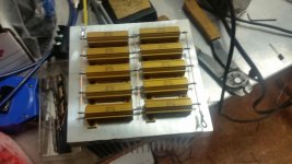
I did a series parallel configuration with 10 20R 50W power resistors on a fan cooled DIY heatsink for my dummy load. This configuration allows 2, 4 or 8 ohm loading as well depending on where you connect to it. I have my own milling machine, which helps with building the heatsink.
Attachments
Okay, from what everyone is telling me I have to throw down a bit of money here.
Before I get to my next question, however, In the video I posted earlier, his resistance of the elements always remained the same despite temp? How so?
https://www.youtube.com/watch?v=5gAUuLkc1ik (Watch from around 5:10 when he does his hot temperature reading)
Anyhow, Is it better to get the metal clad resistors or the hollow ceramic? And what would be the best ohms to get a configurable load?
A resistor like this:
RBEF03008R000KFB00 Vishay / Milwaukee | Mouser
Or one like this:
HS250 8R0 1% Arcol | Mouser
Thanks for all your help.
Last edited:
Get 10 of these and mount them on a heatsink. RH05020R00FC02 VISHAY DALE Panel / Chassis Mount Resistors | 01F9920 | Newark element14 Canada Parallel 5 of them gives you 4 ohms. Series 2 sets of 5 paralleled gives you 8 ohms @ 500 watts power rating. The key is to keep the temperature stable so the resistance doesn't deviate. Use large heatsink and a fan.
Okay, from what everyone is telling me I have to throw down a bit of money here.
Before I get to my next question, however, In the video I posted earlier, his resistance of the elements always remained the same despite temp? How so?
https://www.youtube.com/watch?v=5gAUuLkc1ik (Watch from around 5:10 when he does his hot temperature reading)
Anyhow, Is it better to get the metal clad resistors or the hollow ceramic? And what would be the best ohms to get a configurable load?
A resistor like this:
RBEF03008R000KFB00 Vishay / Milwaukee | Mouser
Or one like this:
HS250 8R0 1% Arcol | Mouser
Thanks for all your help.
The key is not so much how the metal is deployed, but what metal it is.
Metals with near zero temperature coefficient seem to be readily available and widely deployed, you just have to dodge the substandard parts many of which are specifically sold as "power amp loads".
IME Vishay and Arco know how to "Do it right". Given the business they are in, they better! Check eBay as there are relevant products for attractive prices. Beware, there is some mystery meat there.
To me the most improbable amp dummy loads are water heater elements, but if you watch the power rating and voltage rating you can come close to standard values and the tempco on the devices I and others have tested are very usable. Besides, they are water and oil proof, so fluid baths can be used to keep them cool.
Remember, non-inductive construction is also important.
Last edited:
what do you want to look for with the dummy load? - no real need for extreme stability given the practical application is driving copper or aluminum voice coils that vary few 10% from self heating
a small value current sense R of good quality but only few % of the main load R should give adequate accuracy if needed
the most effective test of a amp's output is a another bigger amp on the other end of the load R to move it in coordination with the tested amp's signal to vary effective load R, simulate complex Z with phase shifted drive signals
frequency and amplitude sweeping the other amp with the test amp at zero gives an easy measure of complex output Z of the tested amp
or even wring out the tested amp's behavior with a relatively prime frequency ratio drive signals to look for "interface" IMD - can be a very stressful test because it walks the output I,V over an extreme range
Hi jcx,
Oh man!
Yes, you are absolutely correct. This takes too much time to set up, and you could always turn the tested amp into a load at 1 AM. The Duh hour. 🙂
-Chris
Oh man!
Yes, you are absolutely correct. This takes too much time to set up, and you could always turn the tested amp into a load at 1 AM. The Duh hour. 🙂
-Chris
Hi Gamerandds,
You have a few good suggestions from members here. You have to choose between a little $$ and something complicated to set up. You don't want to make a mistake when you are tired.
From the point of view of a technician, you want something simple that you don't have to worry about. Grab two pair of either 8 or 4 ohm resistors rated for 100 watts or more. Then you can simply use them without any worry. You could use advice from jwilhelm on post 16. Just set them up as 4 or 8 ohms and set two pairs so you can quickly use either impedance. 4 ohm resistors also allow you to use 2 ohm loads if you need that. Keep in mind that you would probably be tripping breakers with these large amplifiers.
I used the metal Dale resistors for two reasons. They stay more cool, they were the expected load to use (Marantz / Superscope preferred these parts). However, this is probably the most expensive route you could take. Don't waste your money either, so the tubular types could be fine as well. Remember too, finishing the rear of heat sinks is expensive. So keep these costs in mind.
Simple question that turned up some great information and wonderful suggestions from everyone. If I had not already gone through this, I think I would look closely at posts 14, 16 and 18.
In my case, I had a changing group of technicians using this equipment. KISS!
-Chris
- Status
- Not open for further replies.
- Home
- Amplifiers
- Solid State
- Amp Output Testing