smps powered amplifier ground wire noise
Hi folks, So I essentially built the apex h900 version but after the 2sc5200/2sa1943 pairs kept blowing I realized that even though the author suggests using +-110v rails that is too close to the SOA of those transistors and just disabled the rail switching and now use it as a simple two rail amplifier.
+-90v rails.
Now even though the original schematic doesn't use a resistor to lift the signal ground from the psu ground , ir rather suggests on tying them together I first had big hum in the speakers, then I lifted the signal ground from the psu ground using 10 ohm resistors for each channel , so no i have a common point at the psu were 3 wires of ground all connect , one goes directly to speaker output , the other two for each channel, then on each channel a signal ground via that 10ohm resistor goes through the volume pot to the input RCA terminal were they join together.
This seems to work but still I get a small yet audible hiss/hum like mix in the speakers.So I can't seem to find out were else it is coming from.
Also I have the connections for the bridge switch, he wires come from one channels A connections to the other channels B pin.I do use screened wire for those connections just that I dont attach that screen to the signal ground rather directly to the psu ground so that in case there are some ground current sit wont mess with the signal path, even then i too added a resistor in series with that wire.
Also maybe there need to be some more capacitors on the driver stage in this circuit across the transistors or maybe some values of the existing ones should be changed ?
As in most this diy stuff all these schematics do lack something sometimes maybe a simple thing but kinda feels like it's done on purpose to make those replicating it think for themselves which i'm already doing here.
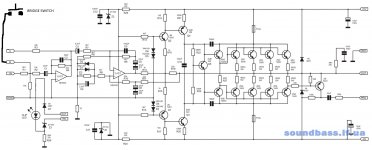
I have added my bit modded circuit schematic , it shows the signal ground resistor etc, also maybe in parallel with that resistor I should put a small value capacitor?
Hi folks, So I essentially built the apex h900 version but after the 2sc5200/2sa1943 pairs kept blowing I realized that even though the author suggests using +-110v rails that is too close to the SOA of those transistors and just disabled the rail switching and now use it as a simple two rail amplifier.
+-90v rails.
Now even though the original schematic doesn't use a resistor to lift the signal ground from the psu ground , ir rather suggests on tying them together I first had big hum in the speakers, then I lifted the signal ground from the psu ground using 10 ohm resistors for each channel , so no i have a common point at the psu were 3 wires of ground all connect , one goes directly to speaker output , the other two for each channel, then on each channel a signal ground via that 10ohm resistor goes through the volume pot to the input RCA terminal were they join together.
This seems to work but still I get a small yet audible hiss/hum like mix in the speakers.So I can't seem to find out were else it is coming from.
Also I have the connections for the bridge switch, he wires come from one channels A connections to the other channels B pin.I do use screened wire for those connections just that I dont attach that screen to the signal ground rather directly to the psu ground so that in case there are some ground current sit wont mess with the signal path, even then i too added a resistor in series with that wire.
Also maybe there need to be some more capacitors on the driver stage in this circuit across the transistors or maybe some values of the existing ones should be changed ?
As in most this diy stuff all these schematics do lack something sometimes maybe a simple thing but kinda feels like it's done on purpose to make those replicating it think for themselves which i'm already doing here.
I have added my bit modded circuit schematic , it shows the signal ground resistor etc, also maybe in parallel with that resistor I should put a small value capacitor?
Attachments
Last edited:
Most likely - overall wiring issue.
Here is an excellent material by Bonsai:
HOW TO WIRE-UP A POWER AMPLIFIER
If you show your wiring diagram, outlining ALL connections, we can probably come up with some suggestions...
Here is an excellent material by Bonsai:
HOW TO WIRE-UP A POWER AMPLIFIER
If you show your wiring diagram, outlining ALL connections, we can probably come up with some suggestions...
Ok I think I found the problem, I searched for ground currents with a scope and while attaching the scopes ground to the common ground point at the psu and then probing the lead to either the speaker output terminal ground or signal ground or any other ground that spans some length I got some parasitic spikes on the scope. they are not as high as the switching frequency of my smps that powers the amp but lower harmonics probably that are induced in the wires.
how could I eliminate them except building a total faraday enclosure for the amp section?
Maybe I should use some polyester high voltage caps across the +-rails and ground rail coming out of the psu?
the very DC voltage is clean it's filtered but the ground wire coming directly out of the smps transformer and going to the smoothing capacitor midpoint has these spikes on it somehow.
Or could you try to move your SMPS a little farther from the amp?
I tried this with my troids when I had hum problems jsut to ensure whether it's an inductive or a GND wiring problem.
I tried this with my troids when I had hum problems jsut to ensure whether it's an inductive or a GND wiring problem.
It would be quite hard for me to move anything because both he smps and the amp channels are in the same box which i custom made out of aluminum to save space on heatsinks.
there is some space from the psu between the channels some 10cm.also i could add some think perforated metal sheets to cover the psu but I don't think that the field there is so high that this literally happens out of inductance because the amp when playing music is actually quite fine , it doesn't distort or anything it just has this small background noise like a hum that is run through by some radio station changing type high frequency noise.
I will measure more later , maybe I can get this thing off of the ground wire by some clever means.
Hi Guys
As detailed elsewhere, a SMPS is the worst type of supply to use to support a linear amplifier. The output impedance is high and variable rather than low and uniform as is required.
Things can be settled down very nicely using a filter between the SMPS and the linear amp. The ideal is an active hum filter, but this represents significant silicon and potential for waste heat for a large amp like this one. The alternative is a CLC filter.
As with using two linear supplies, using a separate SMPS for each rail is a compromise of material and requires a PSU that is twice the size required compared to a normal split-rail supply.
Have fun
I built an amp with a very similar output circuit.
At first I got oscillation on the output too.
I found Q1 needed a 100pf from collector to base.
The problem is the lower driver has gain where as the upper one doesn't.
At first I got oscillation on the output too.
I found Q1 needed a 100pf from collector to base.
The problem is the lower driver has gain where as the upper one doesn't.
Aside from any ground loop issues, that amplifier topology requires both Miller compensation (cap from collector to base on the VAS - do it symmetrically on both) AND a small lead comp cap from the VAS output (not speaker out) to the feedback summing junction. Lead comp will vary depending on the closed loop gain and is usually pretty small (less than 20 pF). Minimize small signal square wave ringing to tune the cap - layout parasitics that are NOT simulated will affect it in unpredictable ways unless you do a full RF simulation and your models are valid up there.
Running high fT outputs at really high voltages tends to make the stability problems worse. Often it's easier to stabilize on lower rails.
Running high fT outputs at really high voltages tends to make the stability problems worse. Often it's easier to stabilize on lower rails.
Well Struth 'm not sure why would you say the smps is the worst type of supply for a linear amp. Heres the deal, aside from the smps being close to the amplifier the very DC voltage is clean and steady and even under load it drops less with only 2x470uF caps per rail than it would with a similarly sized transformer and you can feel that it does pack some punch through the speakers.
I mean even with that small noise i'm having in the background otherwise it sounds not bad.I definitely had problems using transformers too because large transformers especially EI types radiate quite alot of mains 50hz and getting rid of that HUM is also quite a task.
@nigelwright7557 and wg_ski, could you guys please say more specifically what value capacitance should I use on the VAS stage from C to Base? I had this thought too but before I proceed i wanted to make sure.
100pF ceramics come to mind?
I definitely need to do some compensation in the amp itself as I do believe this design needs some tuning at the user level beacause the schematics as they are are somewhat incomplete either deliberately or by accident, like for example it had no signal ground resistor only a capacitor that was kind of useless because psu ground was supposed to be tied both to amp ground and signal ground at the same time and in no way that can get good results.
As for the parasitic harmonic on the ground wires , I;m not yet certain , well i guess i should compensate the amp first and see what happens but it feels like that parasitic there is actually from the smps, the question is if it's from the smps how to get rid of it?
right now im having the smps with two separate transformers , each two channels use one transformer , right now im having only two channels inside. the transformer is simple 6-0-6 turns of wire secondary.both ends go through a high frequency diode bridge , the middle point tied directly to the cap filter bank, as the rectified rails, so I get 90-0-90 output voltage.
I do have some idle resistors (15k) across the 90-90 connections to limit the maximum idle voltage , otherwise it climbs over 200v DC.But I dont have any resistors from the +- rails to the ground point, maybe i should have some , together with a capacitor? should I use a resistor and cap in series ?
i mean if that parasitic is on the ground wire I doubt its purely induced there , maybe it's just not filtered out properly so I could somehow manage to filter it out at the psu connection board were the wires carry on further to the amp itself?
thank you for your help.

@nigelwright7557 and wg_ski, could you guys please say more specifically what value capacitance should I use on the VAS stage from C to Base? I had this thought too but before I proceed i wanted to make sure.
100pF ceramics come to mind?
connection board were the wires carry on further to the amp itself?
thank you for your help.
I usually use about 100pf
- Status
- Not open for further replies.
- Home
- Amplifiers
- Solid State
- amp oscillating , possible ground loop