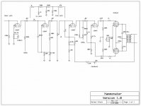
Here is a schematic of a converted amp I'm working on. I 'broke' the circuit and inserted another gain stage from within the chassis which is the second half of the 12ax7 going from left to right. The original circuit is above the new gain stage. The original circuit fed a reverb tank at this point. I inserted the gain stage as shown from the return from the reverb tank. I inserted the 1M pot for a volume control as shown.
I have a few questions about this circuit:
1] first off, is there anything I need to do in the 'duh' mode as far as the hack of the new gain stage? Any components way off value/unnecessary?
2] Can I just add another 1M between the .02 interstage and the 1K resistor prior to the second stage? as another gain control?
3] Can I drop another pot somewhere just prior to the inverter to act as a master volume?
4] as I crank the one gain pot, the next stage distorts [good] but the highs begin to drop off. In fact, overall the frequency response seems to tend toward the lows. Fixes or change in value of existing circuit to remedy?
5] Tone control ideas?
BTW this little circuit worked great as a clean amp prior to my mod, and now with the extra gain stage the amp cranks. I think I'm in love..
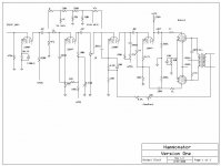
Need to fix your schematic to reflect the circuit you actually installed, what you've drawn can't work. That added stage needs a source of B+, a grid bias resistor, and a separate path for cathode current to ground. (350 ohm resistor is also too small for use with 12AX7 typically) I assume of course that what you added and what you have drawn are not one and the same.


I'm assuming you neglected to show the grid bias resistor on the second 12AX7A stage, something on the order of 1M to ground is in order if it's not there. Otherwise this schematic makes a bit more sense.. 😀

I hope it wasn't a working organ once! Keep the spring reverb, if it's a gibbs part, it's worth it...probably 8ohm input to ?k (high impedance) output. I hope you wrote down the circuit values for that reverb driver, Hammond & co. *invented* the spring reverb.
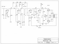
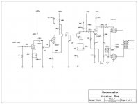
Latest version reflects many changes including dumping a bunch of bypass caps, feedback circuit, guitar-style input voltage divider, etc. One thing that is missing from this schematic is my trial replacing the second volume control with a bandaxel [sp?] bass/treble control. Also not shown is the fact that I added some little niceties like a power switch, lamp, standby switch and fuse.
The gain is great, too great in fact, and I'm thinking voltage divider right after first [now only] volume control?
BTW this little amp started out pretty tame but has grown into a little screamer!
The gain is great, too great in fact, and I'm thinking voltage divider right after first [now only] volume control?
BTW this little amp started out pretty tame but has grown into a little screamer!
Attachments
- Status
- Not open for further replies.
- Home
- Amplifiers
- Tubes / Valves
- Amp Hack schematic questions