In a fit of boredom and in the knowledge that there are some sources of sockets to plug them into, I have been pondering what it would take to make a DIY OTL amp for my Stax SR30 electrets.
The specs for these are 95dB at 100V input, impedance at 10kHz of 150kohm (although there is obviously a capacitive element) which makes it look like an OTL design based around a valve used for driver stages could work. From what is in the parts bin, it looks like 5687s in push pull could work?
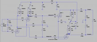
I've atttached a schematic of what the initial back of a packet thoughts are, using 10M45 CCSs as I have had good results previously and it seems to make sense in the context of the output stage requirements. This would presumably lead to an effective loading for the 5687s of 75k each?
The first stage is currently a bit of a throwaway (as I am aware that there are some views on the actual quality of ECC82s...) to show what sort of first stage gain would be required for a reasonable output. In any case, I am not yet sure whether this would go in a system with a balanced preamp or not.
So before anything more goes into the design such as operating point tweaking, are there any points of complete idiocy that I have failed to spot in this context?
The specs for these are 95dB at 100V input, impedance at 10kHz of 150kohm (although there is obviously a capacitive element) which makes it look like an OTL design based around a valve used for driver stages could work. From what is in the parts bin, it looks like 5687s in push pull could work?
I've atttached a schematic of what the initial back of a packet thoughts are, using 10M45 CCSs as I have had good results previously and it seems to make sense in the context of the output stage requirements. This would presumably lead to an effective loading for the 5687s of 75k each?
The first stage is currently a bit of a throwaway (as I am aware that there are some views on the actual quality of ECC82s...) to show what sort of first stage gain would be required for a reasonable output. In any case, I am not yet sure whether this would go in a system with a balanced preamp or not.
So before anything more goes into the design such as operating point tweaking, are there any points of complete idiocy that I have failed to spot in this context?
Attachments
Have a read here MrKettle ,
the website is no longer in business but a memorial website shows 2
OTL designs for electrostatics /electret headphones .
All-Triode Direct-Drive Tube Amps for Electrostatic and Electret Headphones. – HeadWize Memorial
I have a Stax -007 (old version ) but I am not impressed with Stax,s solid -state energizer designs nor their tube versions.
Costly business nowadays !
You have the active loads in the wrong place. R1 should be an active load, as should R9. This will provide exceptional AC balance.
Raise your B+ to 500V. Set your output stage CCS so that 1/2 the current through your plate loading resistor lands your 5687 plate voltage at about 275V.
Raise your B+ to 500V. Set your output stage CCS so that 1/2 the current through your plate loading resistor lands your 5687 plate voltage at about 275V.
You would need some high Vf pull up and pull down diodes in the output section to equalize the widely varying impedance of electrostats from low freq to high freq.
Stax amps have really really nice exposed glass diodes.
A bootstrap (feedback) and output diode would be really nice also if you can source a zener that exists like that.
Stax amps have really really nice exposed glass diodes.
A bootstrap (feedback) and output diode would be really nice also if you can source a zener that exists like that.
Last edited:
This is more nonsense.You would need some high Vf pull up and pull down diodes in the output section to equalize the widely varying impedance of electrostats from low freq to high freq.
Stax amps have really really nice exposed glass diodes.
A bootstrap (feedback) and output diode would be really nice also if you can source a zener that exists like that.
Please explain how with detail and counter points. I would rather the guy stay safe than have electrostats short out on his/her head.
Please explain what function these diodes would perform.
Simply using a zener to as a voltage clamp would require some very careful testing to find an appropriate voltage.
Noone wants to listen to the clipping a premature diode clamp would cause.
A proper crowbar circuit may work better. (Not that it would sound any better at cut off threshold)
Simply using a zener to as a voltage clamp would require some very careful testing to find an appropriate voltage.
Noone wants to listen to the clipping a premature diode clamp would cause.
A proper crowbar circuit may work better. (Not that it would sound any better at cut off threshold)
Last edited:
Please explain what function these diodes would perform.
Simply using a zener to as a voltage clamp would require some very careful testing to find an appropriate voltage.
Noone wants to listen to the clipping a premature diode clamp would cause.
A proper crowbar circuit may work better. (Not that it would sound any better at cut off threshold)
I wonder if theres better ways to protect the driver?
Maybe, maybe not
The only glass diodes in any stax amp ever made are 1n914 and they are in the input stage. The T2 also has 1n914 diodes in the servo.
The current sources in the output stage are in the right place.
The current sources in the input stage can be as shown, or in the tail.
Some feedback is required.
The current sources in the output stage are in the right place.
The current sources in the input stage can be as shown, or in the tail.
Some feedback is required.
Please explain how with detail and counter points. I would rather the guy stay safe than have electrostats short out on his/her head.
The outputs of the amp are at 0V DC. He has not drawn any bias supply, so you can't say much about safety. The gain of the amp is limited to the mu of the triodes.
SR30 are electret and do not require a bias supply.
5.1K series resistor on the outputs is a really good idea although the blocking capacitor takes care of any possible DC on the outputs.
5.1K series resistor on the outputs is a really good idea although the blocking capacitor takes care of any possible DC on the outputs.
That explains a lot. Ignore my irrelevant comments.
It's a nice looking design, from my novice viewpoint (still havent found the time to learn enough Spice)
I've never tried to use a CCS in the tail, but I've tried the anode connection. In that very limited experience, I did find a cascode CCS to work better than a single device, so that may be a possible improvement (questionable).
Should MrKettle want the added complexity, at least.
Ok, I guess I understand. It's not using a bias for the electret.
I am pretty sure what I did describe is a crowbar circuit.
I am pretty sure what I did describe is a crowbar circuit.
Yes, this is for electrets rather than electrostatics hence no bias supply at this point. I am also not necessarily aiming for as high a voltage swing as would be available from 500V B+ given my normal listening levels.
In terms of the other recommendations, output resistors presumably prior to the output caps? Feedback - the sim didn't come out with horrific distortion indications at those levels, but would it just be a case of some local anode to grid feedback round each valve to set gain?
In terms of the other recommendations, output resistors presumably prior to the output caps? Feedback - the sim didn't come out with horrific distortion indications at those levels, but would it just be a case of some local anode to grid feedback round each valve to set gain?
Last edited:
A 1 mega ohm resistor across the output cap pins would also help.
Low value output resistor would be really nice. I'd split the chosen value and put one before and after the output cap also with 1 mega ohm shunts to ground at the cap pins.
This is because the electrets will build bias voltage inherantly over time. Shunts and bleeds will help it to level off somewhere lower.
I also really like to use bleeder resistors whenever using electrolytic output caps.
That and a output transformer big enough to have the proper dielectric voltage separation between windings for a biased electrostats would not be something id want on my head.
Last edited:
No, it doesn't. Making a good cap act like a leaky one doesn't help anything.A 1 mega ohm resistor across the output cap pins would also help.
R6/R7?This is because the electrets will build bias voltage inherantly over time. Shunts and bleeds will help it to level off somewhere lower.
R6/R7?I also really like to use bleeder resistors whenever using electrolytic output caps.
Why would the transformer be on your head?That and a output transformer big enough to have the proper dielectric voltage separation between windings for a biased electrostats would not be something id want on my head.
Some feedback is required.
Just to check on this, is it to reduce the output impedance or reduce nonlinearity? I fiddled about with some shunt feedback around the 5687 stage last night (with an ECC81 input stage to have the same sort of overall gain) and there wasn't any obvious change in the level of 3H in the current through R8.
Have you lost the SRD-4 transformer-coupled adapter?
Still got it, I am just wondering what else I can do with the phones. There are also two systems which I could use the phones in, and moving the adaptor each time is a bit of a hassle.
Last edited:
- Home
- Amplifiers
- Tubes / Valves
- Amp for Stax electrets - 5687 outputs?