ESC quantum Q602 module driver unknown!
the 2 outputs speaker works but
the QA7 irf640 burns intantanemant
measures:
vacuum amps consumes 1.79 amperes
QA7 irf640: 1 -27.36 volt dc 2: zero volt dc 3 -36.17 volt dc
QB7 irf640 1 -36.17 volt dc 2 zero volt 3 -36.04 volt dc
on the unknown module:
next to irf640 burn
Q23 bipolar 2222: 1 8.94 volt dc 2 9.39 volt dc 3 9.04 volt dc
Q24 bipolar 2222: 1 8.49 volt dc 2 8.94 volt dc 3 90.4 volt dc
q25 bipolar 2907A 1 8.49 volt dc 2 9.39 volt dc 3 -9.09 volt dc
on unknown module:
next to the irf 640 fontionnel
q23 bipolar 2222a: 1 0.85 volt dc 2 0.75 volt 3 9.04 volt dc
q24 bipolar 2222a: 1: 0.94 volt dc 2 0.87 volt dc 3 9.04 volt dc
q25 bipolar 2907a 1 0.44 volt dc 2 0.77 volt dc 3 -9.08 volt dc
[/ATTACH]
Attachments
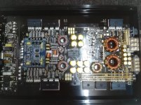
i have unsolder and check:
the 3 transistors on the left then
the 3 transistors on the right of the Dlogixs board
they are good
I will measure the small card in the center with black epoxy glue
there is a big difference of input signal
the 3 transistors on the left then
the 3 transistors on the right of the Dlogixs board
they are good
I will measure the small card in the center with black epoxy glue
there is a big difference of input signal
thanks Perry Babin for your help!
I'm not going to touch the black epoxy just make measurements by injecting a signal 20hz 80 milivolt and follow the signal
I'm not going to touch the black epoxy just make measurements by injecting a signal 20hz 80 milivolt and follow the signal
.jpg")

here are the measurements with a signal 30 Hz 80 millivolt on rca
amp on 12.7Volt 1.7 amperes
speaker output 1.7 volt 30Hz
see photo attached
I also made the measurements on connector down left
1: 41.4 milivolt DC
2 Si: 89 milivolt 30Hz
3 +45: + 31.30 Volt DC
4 -45: - 31.40 volts DC
5 G: 47 milivolt Dc
6 +10: +9.05 volt Dc
7 -10: -9.07 volts dc
the right connector has the same value
I'm going to measure the 6 transistors: q23 q24 and q25 right and left
I removed the 6 q23 q24 q25
the amp works without!
B + 12volt 4.01 ampere
signal 30Hz 32 milivolt at the RCA
output hp 2.77 volt 30Hz
the amp is warm for 3 hours
measurement on empty slot: black probe on RCA shield
to the left
q23:
1: 2.82v 100hz
2: 9.36v dc
3: 9.01 vdc
q24:
1: 40milivolt 60hz
2: 3.35volt 100hz
3: 9.01volt dc
q25:
1: 40milivolt 60hz
2: 9.36 volts dc
3: -9.12 volts dc
to the right
q23:
1: 1.95volt 100hz
2: 9.36 volts dc
3: 9.01volt dc
q24:
1: 42milivolt 60hz
2: 3.02 volt 100hz
3: 2.01 volt dc
q25:
1: 42 milivolt 60hz
2: 9.35 volts dc
3: - 9.12 volt dc
i also measured voltage and frequency from b3 to b7 and a3 to a7
if you are interested ?
Did you try installing 3 for one side or the other (not both) to see if you could narrow down the problem area?
I resolder: q23 q24 q25 right
the amp is working normally
measurement on QB7: irf640n
1: -34 volt dc
2: 2.0 volt 8.9Khz !!!!
3: -35.11
still strange the amp works with fewer components?
it misses on the left QA7, q23, q24, q25!
the amp is working normally
measurement on QB7: irf640n
1: -34 volt dc
2: 2.0 volt 8.9Khz !!!!
3: -35.11
still strange the amp works with fewer components?
it misses on the left QA7, q23, q24, q25!
I changed by new q23 q24 q25 left channel
a new irf640 the amp goes into red LED protection !!
without the irf650 the amp works normally?

a new irf640 the amp goes into red LED protection !!
without the irf650 the amp works normally?
when removes q23 q24 q25 from the right
the fuse 10 amperes burns!
when I go up q23 q24 q25 right
the amp works normally!
the fuse 10 amperes burns!
when I go up q23 q24 q25 right
the amp works normally!
i have found a newer module dlogics AD100W for an ESX amp of the same series
with the same failure


with the same failure
- Status
- Not open for further replies.
- Home
- General Interest
- Car Audio
- amp ESX quantum Q602 module driver unknown!