The Quad 303 design ( 1970 or so ) had these unique features:
regulated single rail power supply
quais complementary triple cascade topology
inverting
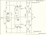
The present design has dual unregulated supply but regulated supply for driver stage
the triple cascade is complimentary
the amp is inverting
the attached schematic has the defaults of the schematic editor
regulated single rail power supply
quais complementary triple cascade topology
inverting
The present design has dual unregulated supply but regulated supply for driver stage
the triple cascade is complimentary
the amp is inverting
the attached schematic has the defaults of the schematic editor
Attachments
Yes a resistor between the blue LEDs is recommended😉
the value is 20 k
with the preliminary PCB layout the value of R30 cannot be larger than 2 k thus a buffer opamp is required in input. With higher values for R30 the transient response shows overshoot and ringing.
Transistors T6,T7 determine the quiescent current and its stability
I put these in a kind of micro oven that is the junction temp. is kept at 70°C .
The quiescent current is set to 50 mA for test purposes. After sine wave packets 8 on 8 off at 1/2 max power in 4 ohms it does not
run higher than 52 mA.
That looks promising.
A more general problem is as follows:
the Quad 303 was designed thus that fT of the active devices increases from output to input.
This is a design directive according to tube amps, if the output transformer is taken into account.
In the present test device the output transistors are the good old
2SA1216 2SC2922 and the drivers are 2SA968 2SC2238
just because I've got a bag full of these for almost nothing.
These will require a sophisticated SOA protection.
More rugged transistors with higher Pd and lower fT could get along with only short circuit protection.
Dieter F.
- Status
- Not open for further replies.