Hello there, I’m new here so i apologise in advance if this has been posted before. I have searched the site and i couldn't find what i was looking for as i think this forum may be a bit advanced for what i am after. Again, i apologise if this is the case.
Basically i want to get into audio electronics and to start with i just want to make an amp for my mp3 player. I have some TIP31A and TIP32A BJTs and a small 8 ohm 800mW driver (nothing special but it's a start).
I want to start with a simple class A design and then progress to a push pull AB design with a Vcc of 4.5v.
I do have an electronics background and i understand how transistor work and i know the maths as well. I can easily draw up a simple schematic for the amp but where i do stumble is my choice of resistor values.
In all the books i have read, certain things are assumed (for example, collector current). What i don't understand is where these values come from. Why would i chose to have such and such a current? If i knew this starting point then i would know what resistor values to use and could then design and test my circuit.
If anyone could help with this rudimentary problem i would be greatly thankful.
You must be reading the wrong books.
For Class A, the maximum power out is half the no-signal power used from the supply. So 100mA collector current from 4.5V means you can get up to 225mW out. In real life it is not as good as this, as a transistor needs a bit of voltage across is to conduct at all. So you decide what power you want, double it, add a bit more for losses and this is then the quiescent power dissipation in the output stage. This assumes a transformer output. For a collector resistor (e.g. very low power outputs) half of your power goes to the resistor.
Are you sure you know the maths?
Thank you DF96. I knew Ic and output power were related but it didn't occur to me to define my Ic based on the output power i wanted. I thought that there may have been something else that would give me a certain current that i had little control over. Now i know what Ic i want i can draw up a design. Thank you once again.
Power output is where amp design always starts.
Power is most comprehensibly expressed as continuous sin wave power, this is what is meant when a reputable manufacturer advertises an amp as, say, 100 Watts. This is also called RMS power, and it is the same measure as that employed by the electricity company when they charge you for power. Although there are other measures such as peak instantaneous power and PMPO we will ignore them for the moment.
RMS power permits the common Ohms law equation (V = I * R) to be extended to cover power in AC and DC circuits in an exactly equivalent fashion.
In a DC circuit Watts=Amps*Volts (W=I*V). Since Volts=Current*Resistance we can substitute I*R for V in the power equation. Thus W=I*V becomes W=I*I*R or I^2*R (I squared R). I'm going to start omitting some of the multiplication signs (*) now. Rearranging V=IR gives us I=V/R. We can also substitute for I in W=IV to get W=V^2/R (V squared upon R). We now have 2 equations which tell us the required voltage or current in a particular load (speaker) to give a required power output.
In order to fully appreciate the situation is is necessary to distinguish (in AC) between peak, peak-to-peak and RMS measurements. RMS measurements are required to bring the actual power (rate of work) into line with DC measurements.
AC voltages and currents are sin waves. Because they vary around 0 (zero), their average value is 0. An AC voltage with a maximum positive excursion of 1V (and a negative excursion of 1V) has an average value of zero volts. It is said to have a peak value of 1V and a peak-to-peak value of 2V. If the wave were squashed down to occupy a rectangle, the height of the rectangle would be 1 divided by the square root of 2. 1/1.414 approx. or 0.707V. This is called the RMS (or root mean square) value.
Now we can calculate the voltages or currents required to produce (say) 10 Watts in an 8 ohm speaker. The formula for voltage would be W=V^2/R. Substituting the values we have, we get 10=(V^2)/8. Rearranging we get V^2=10*8=80. Hence V=sqrt(80)=8.944V. This however is the RMS value. In order to obtain the peak value we must multiply by sqrt(2) or 1.414 with the result 12.65V. We must then double this to get the peak-to-peak value of 25.3V. This is the voltage swing required to produce 10W (RMS) power in a load of 8R. All other considerations aside the amplifier must be able to produce such a swing across the load, be it between 0 and 25.3V or -12.65V and +12.65V.
It's obviously not impossible to put a transformer in the collector circuit of a BJT, but this is rarely done in an audio amplifier (it's not uncommon in RF output stages). Unless the quiescent voltage is 0V (which means a push-pull amplifier) the amplifier must be AC coupled to prevent DC flowing in the speaker. Transistor output stages may be arranged as common emitter or emitter follower.
Taking the case of the common emitter, for greatest efficiency the output impedance (collector resistor) must match that of the speaker. This means that half the available voltage swing appears across the output impedance and the voltage available to the amplifier must be double that appearing across the load.
We can similarly calculate the peak current required in the load. Since in class A the current varies from zero to twice the peak level, the quiescent current in the stage can be set to the peak level or half the peak-to-peak value. Often the actual value used will be 110% of the peak level and the supply voltages increased by a similar factor to account for losses.
In your case we want 0.8W in 8 Ohms. This gives us V^2 = 6.4V and VRMS = 2.53V. Vpk=3.58V and Vpk-pk = 7.16V so your supply voltage needs to be ~15V (for a common emitter) and the quiescent current ~0.5A for class A.
Unfortunately you will find that designing a common emitter amp with 8 Ohms in the collector circuit has its own problems. It's easier in many respects to take an opamp with rail-to-rail capability and drive an emitter follower or effectively design a discrete rail-rail opamp and follow that with an emitter follower.
w
Wow, that was very indepth. Thank you! as i am limited to using a Vcc of 4.5v and an 8ohm 0.8W speaker, i calculate a quiescent current of about:
I = sqrt(0.8/8)*1.414 = 450mA
Therefore Rc should be about 2.25/0.45 = 5 ohms.
Is this correct? if so then i know that i am on the right path.
Thank you wakibaki.
I = sqrt(0.8/8)*1.414 = 450mA
Therefore Rc should be about 2.25/0.45 = 5 ohms.
Is this correct? if so then i know that i am on the right path.
Thank you wakibaki.
RMS power permits the common Ohms law equation (V = I * R) to be extended to cover power in AC and DC circuits in an exactly equivalent fashion.
It is probably an already lost battle, but RMS power doesn't exist. Or at least, it is not the product of RMS volts by RMS amperes. This product yields an average power.
One could apply the mathematical RMS process to power (or to any other quantity), but the result has, to my knowledge no physical meaning.
I have been trying to think of an example where RMS power would be an accurate term, but I can't think of one yet. I think it probably is a lost battle, but muddled language sometimes leads to muddled thinking.
Squashing a sine wave down to occupy a rectangle is a poorly defined procedure. RMS arises from equal power, averaged over a complete cycle; you divide by sqrt(2)=1.414. If instead you wanted equal average voltage/current over a half-cycle you would divide by pi/2=1.5708. (Incidentally, the ratio between these two numbers gives you the 90% of RMS for the output of a perfect choke input power supply).
Squashing a sine wave down to occupy a rectangle is a poorly defined procedure. RMS arises from equal power, averaged over a complete cycle; you divide by sqrt(2)=1.414. If instead you wanted equal average voltage/current over a half-cycle you would divide by pi/2=1.5708. (Incidentally, the ratio between these two numbers gives you the 90% of RMS for the output of a perfect choke input power supply).
It is probably an already lost battle, but RMS power doesn't exist. Or at least, it is not the product of RMS volts by RMS amperes. This product yields an average power.
One could apply the mathematical RMS process to power (or to any other quantity), but the result has, to my knowledge no physical meaning.
Exactly how does this kind of quibbling help in this context? You're just obfuscating an already complicated explanation by insisting on a distinction that is widely ignored throughout electronic engineering. There has to be a point at which I limit the detail. If you're so concerned about the exact meaning of terms employed why don't you write a comprehensive explanation yourself instead of sitting on the sidelines nit-picking?
w
Engineering is not about getting things approximately right most of the time.
Why not use VAs instead of watts, or coulombs instead of farads then?
And in this case, there is a very good reason to be accurate.
It is one of the ways overunity cranks "prove" their output power is greater than the input: because the output power of these "machines" is often delivered in short, high power pulses, the RMS power is significantly higher than the average power.
There is a time and place for being accurate as an engineer; time, money, jobs and lives can be at stake. However, this is not it. I appreciate all the help i have received and the depth gone into, but like i have saide before, i do know the maths, my problem though is applying it as you can probably see with the maths in my previous post. I multiplied current by 1.414 when it should have been 0.707 (or so i believe). giving me the following values:
Ic = 224mA
Rc = 10 ohms
Does this look correct?
Ic = 224mA
Rc = 10 ohms
Does this look correct?
Yes, right.
Your first attempt at the current was correct. The peak value of the current is sqrt(2) times the RMS value and the pk-pk value is 2*sqrt(2) times the RMS value.
W=I^2R. I^2=0.8/8. I=sqrt(0.1)=0.316. *sqrt(2)=~450mA
Unfortunately your problems do not end there.
You have 4.5V available. This equates to a peak voltage of 2.25V and an RMS voltage of ~1.6V. W=V^2(RMS)/R
(1.6^2)/8=0.32W
So even if you can contrive to make your amplifier swing 0-4.5V the output power will not exceed 320mW into 8 ohms.
Power output is where amp design always starts. From this you can calculate the supply voltage required for the topology you have chosen. Some topologies will require more than the basic voltage swing required across the load. If less voltage than this is available then an inductor or transformer will be required in the collector circuit. Inductors are more suited to narrowband applications. Transformers are virtually unknown in BJT audio applications nowadays.
Your best bet is to employ a rail-rail opamp and an emitter follower configuration as I suggested earlier, unless you want to get a higher voltage power supply. Set the opamp output to 1/2 Vcc with a voltage divider at the non-inverting input. AC couple throughout. Set the TIP31 output to 1/2 Vcc with a voltage divider at the base. Make the current through the divider 10 times the quiescent current divided by the TIP31 gain. You can use equal valued resistors and a diode to get 0.6V positive offset. The emitter will settle at the base voltage minus 0.6V. Put a resistor from the TIP31 emitter to ground that gives you slightly more than the quiescent current when the voltage across it is 1/2 Vcc.
w
thanks once again waki, you have been a great help, I will try doing that. I have been testing my circuit and it works which is good and it has given me a good base to work with. I will now try what you suggest and also try doing a push pull and see where that takes me.
Thank you.
Thank you.
Hello again, i have been working on my AB amp now for some time and i just can't get it to work. The single ended class A amp worked fine. I made a simple preamp using an lm741, and although it was a bit on the quiet side or distorted (nothing a bit of tweaking etc can't fix) it worked.
However, my AB amp doesn't work at all, no sound. I have been working on this for many many hours now and i just can't figure why it doesn't work.
Here's a schematic of it:
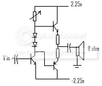
The emitter resistors are about 5 or 6 ohms (smallest i have), the transistors are TIP31A and TIP32A, i have used resistors from 0 to 100K ohms for the variable resistor (to play with). The circuit has been tweaked many times and somtime i can get a bit of sound out but its always very very quiet or very distorted and still quite quiet. For example, if i don't connect the collector of the first transistor, and connect the base of PNP to the base of this initial transistor i get noise. But if i take this transistor out of the circuit completely i get no sound.
I really have no clue why this does not work so if anyone could help me i will be increadibly happy.
However, my AB amp doesn't work at all, no sound. I have been working on this for many many hours now and i just can't figure why it doesn't work.
Here's a schematic of it:
The emitter resistors are about 5 or 6 ohms (smallest i have), the transistors are TIP31A and TIP32A, i have used resistors from 0 to 100K ohms for the variable resistor (to play with). The circuit has been tweaked many times and somtime i can get a bit of sound out but its always very very quiet or very distorted and still quite quiet. For example, if i don't connect the collector of the first transistor, and connect the base of PNP to the base of this initial transistor i get noise. But if i take this transistor out of the circuit completely i get no sound.
I really have no clue why this does not work so if anyone could help me i will be increadibly happy.
Last edited:
sorry, the base of the PNP is connected to the collector of the first transistor, i will edit the schematic now.
Ah. That does make sense. So if i were to have a resistor from V+ to bias it, all will be fine? Having said that, when i have removed the input transistor entirely, i still get close to no sound at all.
Try 100k. This will give you 40uA into the base, 4mA standing current for an hfe of 100. Now you will have a potential on the 2 bases of the output pair which should keep them turned on (just). Tweak the pot to set the junction of the diodes to 0V. The emitter resistors need to be small (1R) and the caps dimensioned appropriately.
w
w
- Status
- Not open for further replies.
- Home
- Amplifiers
- Solid State
- amp design help