I have always worked and listened to class “AB” amps where the class A was until about 1W rms and then after the amp switched to class B for higher level. Class A heats too much to get a reasonable power for me. Just by curiosity I checked the other day with a voltmeter while listening to music what was the power that I needed 99% of the time. I have realized that I do not play my amp louder than about 10Wrms (and this was very loud) in my living room.
Thus, I intent to build a class A / B amp :
Class A until about 15 Wrms / 8 ohms
Class B up to about 50W rms / 8 ohms
The class B would allow me to use the amp for party or else but most of the time I would enjoy class A. Is class A so good compare to good AB?
I thought it would be fun to know when the amp begins to go in class B while I listen to music like with a LED indication.
So I thought that one way to detect the level of music that makes the amp to go into class B would be to measure the AC current in one of the output transistor and compare it with the DC bias current in the same transistor. If the AC current would exceed the DC bias current then a LED would indicate class B operation. Using the usual output transistor source or emitter resistor to measure DC and AC voltages across it could be easy. I have built a prototype and it seems to work (although my actual amp switches to class B at about 1 W. Of course this circuit is only useful with a reasonable class A power. The advantage of that technique - compared to just measuring the AC output voltage and then calculating the power – is that it considers the load impedance since it can vary and also if someone change the DC bias current then no adjustment is required for the Class B detection circuit.
Any comments appreciated?
Hi,
a push pull ClassA amp will deliver almost 2 times Iq into the load before it leaves ClassA into ClassAB.
Say you set Iq = 1A then you have about 1.95Apk into any load and still working in ClassA. Into 8r about 32W, 6r about 24W, 4r about 16w.
A conventional ClassAB amp is often set to an Iq = 10mA to 50mA (like your's). If your heatsinks are large enough it is easy to reset the bias to increase the Iq to about 100mA to 500mA for increased ClassA drive ability. Once you approach the higher end of this Iq range, temperatures start to rise dangerously and you risk SOAR failures. KEEP it COOL.
As you rightly pointed out the ClassA limit is strictly current based and the ClassA output power drops as the load impedance drops.
Your idea to measure the Volts drop across a load monitoring resistor and comparing this to the filtered volts drop on the emitter resistors could be turned into a ClassAB detector.
It may even be possible to avoid measuring the output volts drop and instead measure the fall to almost zero current in either Re and latch on a led indicator. 2 comparators (one for each Re) should be able to be set up to do this.
1A bias in a push-pull amplifier will allow 2A peaks before one device cuts off. That will be 1.414A RMS current, or about 16W ionto 8 ohms.
In a real amp with real losses and a real brute force unregulated supply it will take about ±40V to do 50W into 8 ohms.
1A bias will therefore be 80W heat to get rid of at idle, per channel.
This is about how much heat a 200W class AB amplifier has to get rid of at full power.
Nelson Pass has a patent covering how to reduce this to a sane level in a cacsode output stage. It is a very clever varient of a tiered power supply.
The easiest way to do this would be to run the outputs from a ±12V supply, biased at 1A, shifting to a cascode running from ±40V for peak signals above ±12V.
The power at idle would only be 24W instead of 80W, and the amplifier would run as a cascode above the 16W level.
Douglas Self has such a design, although his site looks like it may be down for now.
OOPS !
DJK is right about rms power.
I quoted peak power by mistake because I forgot to divide by 2.
DJK is right about rms power.
I quoted peak power by mistake because I forgot to divide by 2.
fab said:
I thought it would be fun to know when the amp begins to go in class B while I listen to music like with a LED indication.
In my post http://www.diyaudio.com/forums/showthread.php?postid=282339#post282339 I showed a non-switching class AB output stage with the intention that it will be used for the most part in class A. The post also mentions the possibility and way to add a class A to B indicator.
It was just a basic design idea and it still hasn't found a way into a tangible amplifier, but maybe this will change one day.
Steven
class B detection
Thanks AndrewT, DJK and Steven for your valuable comments.
Your calculations seems to match with mine since the heatsink (SK93) that I have selected is able to maintain about 52 deg C at 90W. I also planned to use +/- 40V dc supply at 1A dc bias current as you suggested.
One thing I would also like is some appreciation if it really worths it in term of sound reproduction (from experience) to do 15W class A and 50W class B while with the same heatsink I could do 200W AB (1W class A). Suppose it is the same amp topology of course between the 2 options.
The cascode output stage idea seems interesting but has someone tried it to see if other problem could arise? Do you remember the patent number? Is it similar to class G?
AndrewT, is it possible that you draw the 2 comparators circuit that you mentioned?
Hi Fab,
You can achieve lower distortions from a WELL DESIGNED amplifier run in Class A because it doesn't have to deal with the x'over discontinuity. Having said that there are mfg's out there who design massive power wasteful Class A designs to produce small amounts of power with sympathetic distortions, for money, while hyping the need to achieve audio nirvana - see Luscious new amplifier thread.
Cheers,
Greg
Fab,
you are probably using Emitter/Source (hereon called E/S) followers as the outputstage!?
Here is one idea of several I see:
If you also have E/S resistors you can add a comparator on BOTH upper and lower resistors, and every time the voltage over the E/S resistors approaches zero you are entering the class-B working area for the output transistors.
And if you wish some persistancy to the reading of the LED light you can add a R/S logic circuit or 555 timer etc etc adding a small delay so the LED wont go off every time the outputstage current makes the zerocrossing(entering the class A region), Obs! it's not the voltage you want to know, thats beacause loudspeakers are not perfectly resistive.
Cheers Michael
Hi Ultima,
were you reading post 2 last para when you wrote that?
I'm glad you made a better job of explaining the method.
were you reading post 2 last para when you wrote that?
I'm glad you made a better job of explaining the method.
Hi andrew,
I dont use to second others idea, but might have missed your 2 last paragraphs in detail, however I also described why, yes, thanks Andrew.
Cheers Michael 😉
I dont use to second others idea, but might have missed your 2 last paragraphs in detail, however I also described why, yes, thanks Andrew.
Cheers Michael 😉
Ultima Thule said:Fab,
you are probably using Emitter/Source (hereon called E/S) followers as the outputstage!?
Cheers Michael
Yes follower mosfet output stage.
Ultima Thule said:
Here is one idea of several I see:
If you also have E/S resistors you can add a comparator on BOTH upper and lower resistors, and every time the voltage over the E/S resistors approaches zero you are entering the class-B working area for the output transistors.
...
Cheers Michael
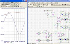
What level would be appropriate for "approaching zero"? It will never cross zero. Here are my simulation results where the first graph show a reasonably clean waveform across the source resistor but the detected peak level is higher than 15 mv.
Attachments
fab said:
Yes follower mosfet output stage.
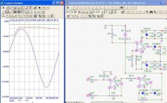
What level would be appropriate for "approaching zero"? It will never cross zero. Here are my simulation results where the first graph show a reasonably clean waveform across the source resistor but the detected peak level is higher than 15 mv.
The second graph shows clearly that the waveform is modified but the detectd level is still about 10 mv or so.
I can compare the detected level with a fixed level but what should it be? or I am completely out of track here?
Note: I only use the negative side resistor since it takes less parts and will do the job (when the level is high on the negative part of cycle it will be also high in the postive part anyway)
V(16): inverted signal across the negatve source resistor (0.18 ohms) and output.
V(1): peak level detected
v(2): threshold of value (the one I fixed arbitrarily to about 5 mv) for comparison to set the LED on.
Attachments
Hi,
I'm not sure if i have read your graph correctly.
Vq across lower Re = 75mV? giving Iq=410mA?
Theoretically it stays in classA if the Vre is always negative ie from -1uV to -150mV but I think it will have started to become more like ClassAB as you approach small Vre
I would think a detection level of falling below 5% to 10% of Vq would be about right ie led on if Vq <4mV but you could easily put in a resistor string with a low value pot to trim the detection point, anywhere between 1mV and 7.5mV.
Remember to use a bridge for detecting the Vre voltage ie. two resistor strings fed from the same source voltage and same sink voltage then the central junction of each string goes to the + & - of the comparator. A real comparator performs slightly better than an opamp and are just as cheap. At the moment you have shown a balanced input opamp with unbalanced input impedances. This is too complicated. Look at detecting differences across a bridge. Once you have the neg. sorted then just mirror image the comparator for the extra pos. detection.
Maybe it is easier to detect the zero current condition at the collector (or drain) side, i.e. with reference to the power supplies. Disadvantage is that you need an additional power resistor (or two).
Steven
Steven
fab said:
Yes follower mosfet output stage.
What level would be appropriate for "approaching zero"? It will never cross zero. Here are my simulation results where the first graph show a reasonably clean waveform across the source resistor but the detected peak level is higher than 15 mv.
Fab,
don't you have current probes in your simulator? It would be more visually clear when the current is going to zero through the Source resistor.
BTW now I see you use LF351 (X2 in your schematic) which is not a comparator, morelse you should not have feedback (R19) between output and (-) input, but rather between output and (+) to give a distinct positive feedback which makes the comparator to have either high or low output, not in the linear region inbetween the rails voltages of your detection circuit.
Try a LM393 comparator or so and sim on.
Cheers Michael
class B detection
AndrewT and Ultima,
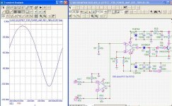
Attached is a simplified circuit getting rid of the peak hold detector. thanks for noticing that since I had already a "holding" circuit in the driving led part of the circuit. It seems to work based on the simulation. In the virtual amp used for simulation I use 2 parallel mosfets so that is why the current is doubled in the output. The simulator gives 66ma bias DC in 0.18 ohm (one of the negative mosfet). So the class A current is 0.733 A which gives 8.6Wrms /8 ohms thus about 11.73 Vac which matches with the detection circuit used. Afterwards, I changed the load to 4 ohms then had to reduce the ouput voltage to about 5.87 Vac to get the detector to indicate class B thus giving 4.3Wrms/4 ohms.
The circuit only monitors the negative cycle (which is fine for me).
Sorry but I have not figured out the use of the resistor bridge with comparators?
The X2 opamp in my circuit is not used as a comparator but as a difference amplifier between source of negative mosfet and output of amp. The comparator is X1. I plan to use old 741 opamp since I have plenty of them and I could not find an application whre they could do the job (where the performance of the opamp was not important).
Hi Steven,
how would it be more simple with reference to the power supplies? As you pointed out this add additional resistor and another potential drop which reduces the efficiency of the amp. Mosfet are not that efficient already...
AndrewT and Ultima,
Attached is a simplified circuit getting rid of the peak hold detector. thanks for noticing that since I had already a "holding" circuit in the driving led part of the circuit. It seems to work based on the simulation. In the virtual amp used for simulation I use 2 parallel mosfets so that is why the current is doubled in the output. The simulator gives 66ma bias DC in 0.18 ohm (one of the negative mosfet). So the class A current is 0.733 A which gives 8.6Wrms /8 ohms thus about 11.73 Vac which matches with the detection circuit used. Afterwards, I changed the load to 4 ohms then had to reduce the ouput voltage to about 5.87 Vac to get the detector to indicate class B thus giving 4.3Wrms/4 ohms.
The circuit only monitors the negative cycle (which is fine for me).
Sorry but I have not figured out the use of the resistor bridge with comparators?
The X2 opamp in my circuit is not used as a comparator but as a difference amplifier between source of negative mosfet and output of amp. The comparator is X1. I plan to use old 741 opamp since I have plenty of them and I could not find an application whre they could do the job (where the performance of the opamp was not important).
Hi Steven,
how would it be more simple with reference to the power supplies? As you pointed out this add additional resistor and another potential drop which reduces the efficiency of the amp. Mosfet are not that efficient already...
Attachments
class B detection practical test
Hello again,
I have modified my prototype to be as my last posted circuit and connected it a pratical class AB amp over biased to about 550 ma. The detector works OK for 8 ohms but for 4 ohms the max detected class A power is about 1/5 of max detected power with 8 ohms!
I have also checked the voltage at output of input amplifier of detector circuit and it is about the same with no load than with 8 ohms load!
What is my balance input amplifier measuring?
The simultor does not show any problem at 4 ohms or with no load.
What am I missing here?
Hi Fab,
ok, I didn't look much beyond X2, sorry for that, but I think you should have at least right type of components in your sim doing the job, at least there it wont cost you anything!
How about the voltage supply for your detection circuit and is the earth same as amplifiers earth?
What Voltage supply do you use for your amplifier?
When sensing the Source resistor and having the first stage (comparator/op-amp or whatever you use) the component must be sufficient due to CMRR especially if the common refference for your circuit is earth.
It would help a bit if you present some information about your amplifier you are going to build, what are the supplying voltage?
If I see correct you use 47 ohm at both input on X2, isn't that a bit tuff condition for that op-amp if the amplifier will swing more than +-15 Volts which seems to be your supply voltage for your sensing cisuitry.
Cheers Michael
Hi Ultima,
The input resistors are 47K ohms.
When I check with the scope, the AC voltage across source resistor is null when no load at output of amp. The problem arises at output of the first stage of the detector. When I have time I could take picture of the scope waveform if need be.
CMRR: I thought about that too before going to sleep. Iwill look more into that. Maybe old 741 is not godd enough even for this application... I will still not be able to use them...
Maybe my grounding is not correct for the measuring circuit.
I use +/- 60 Vdc supply for power amp (modified Hafler DH-200).
Thanks
- Status
- Not open for further replies.
- Home
- Amplifiers
- Solid State
- AMP CLASS A to B detection