I'll be starting with the ACP+ / Whammy to drive the F4 but ultimately using an Aikido pre.B1K + F4 requires some serious high efficiency speakers... 90db/w is not enough. Also, distortion of B1K increases dramatically with gain.
--Tom
Yep. Another tip is to put a dab of rosin onto the solder joint, then apply the braid over that. The flux helps the solder flow and improves the braid's wicking action. Just don't get carried away - a little dab will do ya!Now that's looking more like it!
Desoldering is a bit of a skill, much like soldering (possibly more so), so maybe practice by desoldering those LEDs on that junk board before attacking the ACP+ board.
Word of warning, if you use the desoldering braid (probably the best tool for the job in the solder hasn't flowed all the way through the through hole) whatever you do, don't yank it if sticks to the joint. Pulling at it when it's stuck may result in pulling the pad clean off the board, which will ruin your day. Just reheat it by applying a tiny bit of solder to your iron tip and pressing it gently to the braid to get the heat transfer happening again, then lift it away gently.
--Tom

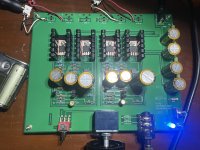
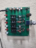
Good day y’all. I was able to finish the build and found the following problems. Appreciate solutions or comments
I was able to pick 2 good j113 fets from 9 parts from digikey and mouser that have higher current across R4. I ended up 2 125ohms in parallel (63ohms) and got 10.76mA and 10.53mA
Other voltages are fine but found the following issues.
1. Sound is a bit distorted and not clean. Do I need to burn in the components? Any thing to check?
2. The rca with gold plating? I ordered does not fit the pcb holes. I could diy or order alternative rca.
3. The switch psu is negative polarity for active centerbpin. Could do re wire . I read the history for this from the build guide
4. Volume control set to max using full
Volume mp3 player or iPhone
I am more concerned in item 1 and 4. Comments and direction appreciated.
Btw I’m using 220v ac line from my solar inverter. Maybe not pure sine wave ac line. I’m checking sound differences to normal Ac line
Attachments
Last edited:
Audible distortion is not normal.
I see only one resistor at R4. Is the other resistor on the underside of the board?
Volume set to maximum is not normal. Was that with headphone out or preamp out? Try a different source. Also check that resistor R14 is correct value.
I see only one resistor at R4. Is the other resistor on the underside of the board?
Volume set to maximum is not normal. Was that with headphone out or preamp out? Try a different source. Also check that resistor R14 is correct value.
Not daft at all.Perhaps a daft question, but do people leave their ACP+ preamps powered on all the time?
Yes, some do, you won’t hurt anything. In fact, the original layout had no power switch, Nelson’s idea was to just leave it powered up all constantly.
Thanks Ben Mah
Yes the 125ohms in parallel is located below the board. It is better to solder there.
The volume set to near maximum is for both my Aca speaker out and headphone out at preamp. Will try different sources and check R14
Yes the 125ohms in parallel is located below the board. It is better to solder there.
The volume set to near maximum is for both my Aca speaker out and headphone out at preamp. Will try different sources and check R14
was
Audible distortion is not normal.
I see only one resistor at R4. Is the other resistor on the underside of the board?
Volume set to maximum is not normal. Was that with headphone out or preamp out? Try a different source. Also check that resistor R14 is correct value.
Update output r14 is 33ohms and not 1k. My bad.
Clarification please: So you had 33R at R14?
Have you replaced it with the correct 1k, and did that fix the problem?
Have you replaced it with the correct 1k, and did that fix the problem?
Here is an update to my post #2,228 above, which was about listening to an ACP+ with a First Watt F7 I bought used. I mentioned that maybe I was hearing some of Nelson's famous second harmonic emphasis in the F7, in comparison to a class AB Denafrips setup. Today I was listening to one of the discussions on YouTube between Nelson and Steve Guttenberg, where they talked about the F7 in comparison to the SIT-3, J2, and F8. Part of discussion was about Nelson's long heritage of second harmonic emphasis going back to the beginnings of First Watt and beyond, BUT also how the F7 (and maybe the F5) was an exception to that being a third-harmonic type of amp. Well so much for my hearing prowess. 🙄
I really do like the F7 and it is living in my main system happily, with the ACP+ preamp. In contrast, the F7 was kind of plain sounding with the Denafrips Athena preamp, which by all accounts is a very good one, with very low measured distortion, and a very fancy volume relay setup, and a very fancy power supply chock full of regulators and capacitors.
Aha! Something the ACP+ is doing makes the overall sound more appealing. Also, it surely can't hurt having the headphone-capable single-ended IRFP610 output setup in the ACP+ giving some dynamic oomph to things. Maybe the second-harmonic character is coming in there? At any rate, another very interesting DIY lesson for me about circuit interactions, thanks to Nelson!
Yes, a good preamp can bring something special to the whole line-up. Nice preamp that Denafrips Athena...and not that expensive.
Yesterday my PCB's have arrived from JLCPCB for building the balanced and upgraded ACP+ 🙂
I made 1 big PCB for the preamp and 6 little PCB's are incorporated for all the auxilary stuff like 'Tactile switch board', 'LED board', 'Servo board' and so on.
Will be fun building that....😀


Yesterday my PCB's have arrived from JLCPCB for building the balanced and upgraded ACP+ 🙂
I made 1 big PCB for the preamp and 6 little PCB's are incorporated for all the auxilary stuff like 'Tactile switch board', 'LED board', 'Servo board' and so on.
Will be fun building that....😀
Nice looking PCBoard! I couldn't find any "vias" (connections between top copper and bottom copper without a component lead). Wow.
There are some in the pads for the SMD relais. And about 2500 connecting the groundplanes top and bottom.
But I see my photo quality is really bad...
But I see my photo quality is really bad...
It is now running bro. It is indeed 1K R14. No change required. The measured low R is board level R. I change my amp from 1watt tube to Aca mini. CheersClarification please: So you had 33R at R14?
Have you replaced it with the correct 1k, and did that fix the problem?
Attachments
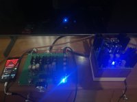
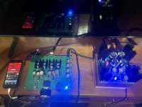
Made some progress this weekend... PSU is working and tested. Now waiting for some components of Mouser to arrive.


This is how it should fit in the casing, looks OK, with few problems to solve 🙂


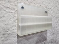
I made a wall mount a while back for my ACA+ and it really works great sitting next to my computer. Here's the link to the 3D printed part if you're interested in doing the same. Print as a solid for best stiffness/strength.
https://www.printables.com/model/634854-amp-camp-amp-preamp-aca-wall-mount
My ACA+ is fed from a DAC, which is fed from USB on my desktop computer. I can hang my headphones on the wall next to the ACA+ and it's all off my desk while remaining fully functional and within reach. It clears up desktop space, looks great up on the wall, and is still easily within reach for operation.
Looking for feedback if it can be improved. Your ACA+ needs the ground plane and rubber feet included with the full kit to mount firmly to the wall. It simply slides into place with a friction fit (no hardware beyond 2 screws for the mount) and can easily be removed anytime since it's just a slide2lock design.
Attachments
Last edited:
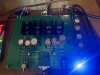
Hello all! Earlier I posted about some static in the right channel I was getting. After trying to look at al my solder joints it turned into NO or very faint sound on the right channel. I replaced all caps on that channel and q3 (wanted to start with the non matched JFET). While doing that I finally found the actual culprit. R4 had a cold soldier joint I'd missed. Resoldered, and it fired right up.
Except one problem- right channel was still noticeably quieter. Turns out I'd replaced q4 with a J112 instead of a J113. Bias on that channel did not match the left channel. No problem, I had an extra J113 from my LXmini crossover board build. Install it, check the bias current across R4. All good!
Or so I thought. I hook it all up, and right channel is dead again. Had sound with a J112 in q4, but nothing after I replaced it with the J113. But bias across R4 reads well. DC1 reads well. No noticeable issues with input or output wiring. What else can I test with a basic DMM here? I love this pre/HPA, but my construction skills seem to have kept it out of service more than I'd like!
- Home
- Amplifiers
- Pass Labs
- Amp Camp Pre+Headphone Amp - ACP+