

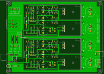
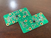
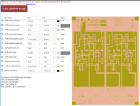
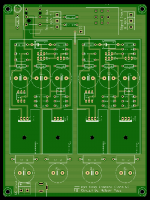
Gerber for my proto board.
I have fixed error in my PCB, sharing gerber for those who are interested in.
BOM differences :
C1 : 106BPA050M
C2 : 16mm dia, 7.5mm LS
C3 : 16mm dia, 7.5mm LS
C4 : 16mm dia, 7.5mm LS
Power filter caps : 13mm dia, 5mm LS
Case : 1455Q1601
Smaller pot (RK16 or DACT) can be used.
All other compoments are same as original.
Attachments
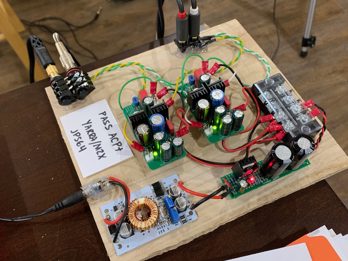
JPS64 Pass ACP+/Yarra M2X Format Boards Tested
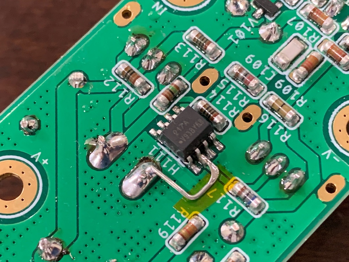
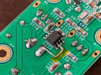
I just completed the verification build on JPS64's PCBs. The SMT side with MELF MMA and MMB resistors was actually fun to make. Definitely use solder paste and a hot plate. The parts per the schematic/BOM work well. There is an error on this prototype schematic and layout that was not caught before we made the PCBs as shown in the schematic. However it was an easy fix to jumper pin 2 to pin 5 on the optoisolator. The production PCBs will have this error fixed. The preamp/HPA sounds great! Listening to it now on my 55ohm OB-1's and they really have a nice powerful dynamic feel and great soundstage. Super quiet - no background noise or hiss/hum. Very nice sounding headphone amp.
A big thank you to Mr Pass for giving us antother great sounding amplifier! And big thanks to JPS64 for a superb layout.
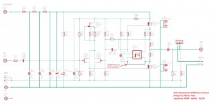
Schematic with Error Fixed:

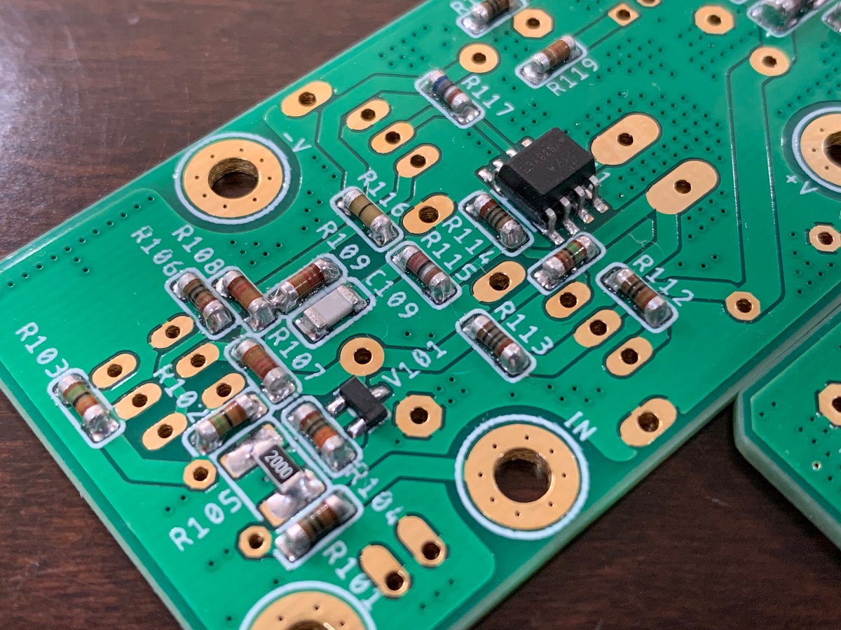
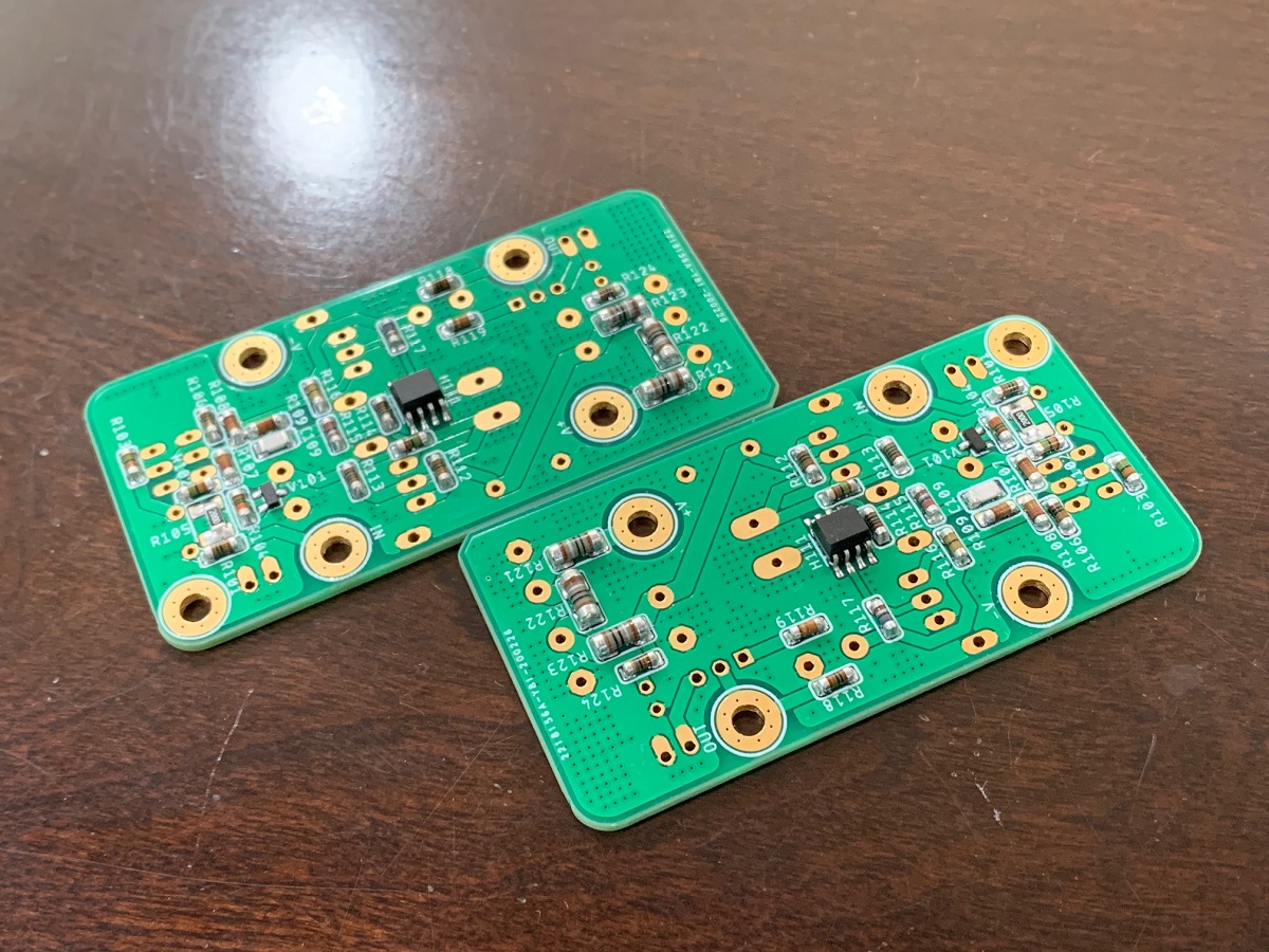
SMT parts populated:

Closeup after cleaning:
Detail of jumper from Pin 2 to Pin 5 (connected to -ve of C111 cap which is same as pin 5):
Topside through-hole components completed:
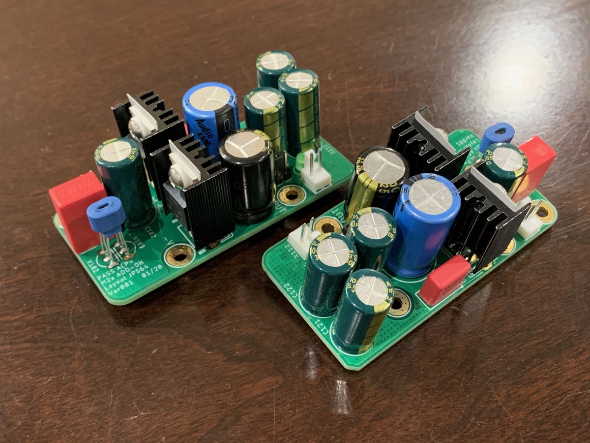
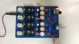
Amp on a plank test fixture with DC-DC SMPS supply and MOSFET cap multiplier for slow ramp up and ripple reduction with 24.0v DC output (measured at amp MOSFET drain):
I just completed the verification build on JPS64's PCBs. The SMT side with MELF MMA and MMB resistors was actually fun to make. Definitely use solder paste and a hot plate. The parts per the schematic/BOM work well. There is an error on this prototype schematic and layout that was not caught before we made the PCBs as shown in the schematic. However it was an easy fix to jumper pin 2 to pin 5 on the optoisolator. The production PCBs will have this error fixed. The preamp/HPA sounds great! Listening to it now on my 55ohm OB-1's and they really have a nice powerful dynamic feel and great soundstage. Super quiet - no background noise or hiss/hum. Very nice sounding headphone amp.
A big thank you to Mr Pass for giving us antother great sounding amplifier! And big thanks to JPS64 for a superb layout.
Schematic with Error Fixed:
SMT parts populated:
Closeup after cleaning:
Detail of jumper from Pin 2 to Pin 5 (connected to -ve of C111 cap which is same as pin 5):
Topside through-hole components completed:
Amp on a plank test fixture with DC-DC SMPS supply and MOSFET cap multiplier for slow ramp up and ripple reduction with 24.0v DC output (measured at amp MOSFET drain):
Attachments
-
 ACP-Yarra-Verif-Build-Photos-01.jpg416.4 KB · Views: 2,443
 -
 ACP-Yarra-Verif-Build-Photos-02.jpg398.7 KB · Views: 2,947
 -
 ACP-Yarra-Verif-Build-Photos-03.jpg365.3 KB · Views: 1,886
 -
 ACP-Yarra-Verif-Build-Photos-04.jpg395.5 KB · Views: 2,944
 -
 ACP-Yarra-Verif-Build-Photos-06.jpg450.6 KB · Views: 2,937
 -
 Pass-ACP-Schematic-rev01b-fix.jpg489.1 KB · Views: 3,109
I have fixed error in my PCB, sharing gerber for those who are interested in.
Thanks for posting the Gerber files but when I upload your Gerber files on the pcbway site I get an error like:
Failed reason:
file cannot opened. gerber/.pcb/.pcbdoc./cam formats are supported(we need gerber file in fomat of RS-274x;
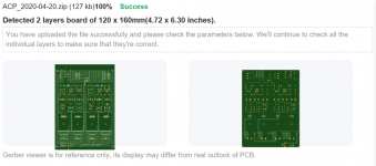
The .zip archive of Gerbers in post #303, reads just fine in the free online Gerber viewer at http://www.pcbxprt.com
_
_
Attachments
Thanks Mark, it works fine on the jlpcb.com site but not on the pcbway.com. Anyway your online Gerber viewer site is good 🙂
Rgds
Rgds
Thanks Mark, it works fine on the jlpcb.com site but not on the pcbway.com. Anyway your online Gerber viewer site is good 🙂
Rgds
I will try to generate gerber once again and check with pcbway! Apology for inconvenience.
I will try to generate gerber once again and check with pcbway! Apology for inconvenience.
Thanks withmatt, it worked with jlpcb and also the online Gerber viewer so no issues. Seems to be some odd file naming or some other issues on pcbway site. Appreciated 🙂
I will try to generate gerber once again and check with pcbway! Apology for inconvenience.
Yes please.

Drills also attached.Thank you!
Attachments

I just completed the verification build on JPS64's PCBs.
SMT parts populated:
I have been listening to this preamp for past couple of days and still really enjoying it. I finally flipped it upside down in order to measure the bias current across R115 and R117 and got 141mA. That's a pretty healthy Class A bias current. It would explain the 76C temp on the little heatsinks that I have.
Last edited by a moderator:
Hi, guys.
Mr. Pass wrote in description, that this schematics does its best with 32 Ohm headphones.
Could you please tell, what changes should be done to get best performance with 300 Ohm headphones?
Mr. Pass wrote in description, that this schematics does its best with 32 Ohm headphones.
Could you please tell, what changes should be done to get best performance with 300 Ohm headphones?
Put a resistor across the headphone output (similar to how R17 is connected for the line output). Use 39R for 300 ohm headphones (= 34R combined resistance)
Thank you, Nisbeth. And what about speaker connection? Nelson wrote, that it is possible. Should I add series resistor to have 32 Ohm in summary?
- Home
- Amplifiers
- Pass Labs
- Amp Camp Pre+Headphone Amp - ACP+