Gentlemen, thank you for your PAYPAL-transfers.
AS I have been told: the current, "new" PAYPAL-application does not permit a "-" sign in the EMail-address (as in RRozek@t-online.de).
PAYPAL will fix this. When?
If you have troubles transferring money to me: use the "old" PAYPAL - design.
Best regards - Rudi_Ratlos
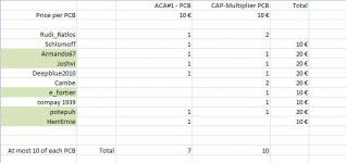
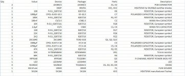
P.S. Find attached the BoM for the CAP-Multiplier as an image.
AS I have been told: the current, "new" PAYPAL-application does not permit a "-" sign in the EMail-address (as in RRozek@t-online.de).
PAYPAL will fix this. When?
If you have troubles transferring money to me: use the "old" PAYPAL - design.
Best regards - Rudi_Ratlos
P.S. Find attached the BoM for the CAP-Multiplier as an image.
Attachments
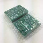
I received the PCBs yesterday and took them to the post-office this morning.
So you will have them in the course of the next week.
Please read Jan Kuetemann's thread: http://www.diyaudio.com/forums/powe...ied-mrevil-pmi-capacitance-multiplier-16.html
before you begin and assemble his CAP-multiplier.
Happy soldering - Rudi
So you will have them in the course of the next week.
Please read Jan Kuetemann's thread: http://www.diyaudio.com/forums/powe...ied-mrevil-pmi-capacitance-multiplier-16.html
before you begin and assemble his CAP-multiplier.
Happy soldering - Rudi
Hi,
PCBs received. Nice, as always. Thanks,
Micha
I received the PCBs yesterday and took them to the post-office this morning.
So you will have them in the course of the next week.
Please read Jan Kuetemann's thread: http://www.diyaudio.com/forums/powe...ied-mrevil-pmi-capacitance-multiplier-16.html
before you begin and assemble his CAP-multiplier.
Happy soldering - Rudi
PCBs received. Nice, as always. Thanks,
Micha
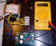
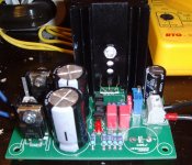
Gentlemen, I soldered Jason Kuetemann's Cap Multiplier (my layout) this morning, connected it to a 18VAC / 650mA R-Core and connected its output to a load consisting of a 100Ohm resistor.
The good news: the output is showing a very stable 22.8VDC (image 1).
I will try and evaluate the ripple-voltage this afternoon.
There are two drawbacks and one question concerning my layout though.
1st: My EAGLE-layout editor has offered me a TO220-case (package) for the pass-transistor IRF9140. I did not check the case, when I did the layout.
But: the IRF9140 is offered in a TO247-case!
No problem for me! I simply cut off part of its legs and soldered a solid wire to the legs (image2). I will ask Jason, if he can recommend a pass-transistor in a TO220-case.
2nd: I did the layout having a 19VDC driven ACA in my mind. Be careful about the input- and output capacitor's voltage range.
3rd: In his thread Jason is talking about an "additional" 2V voltage-drop.
I do not see this, neither in the schematic nor in real-life.
R-Core 18 x 1.4V - Bridge-Rectifier 1.4V = 23.8VDC. So: I am having an additional voltage drop of about 1V instead of 2V.
I will ask Jason.
Nevertheless: this small CAP-Multiplier of Jason seems to be a real gem.
Best regards - Rudi_Ratlos
P.S.: I did deliberately not solder the 3.300µF capacitor on the output. See Jason's thread. I have only soldered the 1.000µF capacitor.
Attachments
Last edited:
Hi Rudi,
The design is pretty tolerant of MOSFET choice, especially true since your target audience will be operating it at lower voltages. So long as Vds and Id are higher than your maximum raw supply voltage and current draw, just get the lowest RdsON specification you can get in your local market. There are no special parameters that need to be met. With a minor resistor value change even a BJT darlington can be used for the pass device.
The 50kΩ adjuster should allow some adjustment range to get the desired voltage drop across the pass device. Operating it at the lower voltage may push the range to one end of the adjustment range. Worst case would require a fixed resistor value in the sampling divider to be changed. Also, the adjustment requires some reasonable load to be attached otherwise the output will seem a little 'shifty' and not responsive to adjustment. The adjustment is also not going to be instant, especially with minimal load, be patient when setting it up.
I hope that helps builders at least a little. Any other questions, feel free to ask.
")
Eric, I have sent you another one a couple of days ago.
Best regards - Rudi
Hi Rudi,
Just received them, thanks !!
Eric
I have upgraded my ACA#1 design to Release 1 to include a simplistic Nelson Pass B1 buffer and make it a "fully integrated" amplifier.
So: my current ACA#1R1 PCB includes:
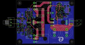
- Jason Kuetemanns CAP-Multiplier PSU (which I operate from a 2x19VAC / 2 x 80VA toroid and adjusted the output voltage to 2 x 24VDC)
- Nelson Pass ACA#1 (the original release, without R15 mod, ..., if you want me to change to a more current release??: tell me)
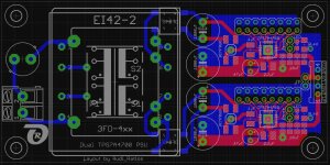
- a simplistic version of Nelson Pass B1 - buffer; the buffer is operated from a dual TPS7A4700 PSU
The size of the ACA-PCB is 100 x 75mm; the size of the TPS7A4700 PCB is 100 x 50mm.
If you are interested to have a pair of my PCBs: tell me.
Best regards - Rudi_Ratlos
P.S.: I do not want to compete with the ACA#1-offer in the DIYAUDIO store.
I simply did a layout to fulfill my Needs and like to share it with you.
So: my current ACA#1R1 PCB includes:
- Jason Kuetemanns CAP-Multiplier PSU (which I operate from a 2x19VAC / 2 x 80VA toroid and adjusted the output voltage to 2 x 24VDC)
- Nelson Pass ACA#1 (the original release, without R15 mod, ..., if you want me to change to a more current release??: tell me)
- a simplistic version of Nelson Pass B1 - buffer; the buffer is operated from a dual TPS7A4700 PSU
The size of the ACA-PCB is 100 x 75mm; the size of the TPS7A4700 PCB is 100 x 50mm.
If you are interested to have a pair of my PCBs: tell me.
Best regards - Rudi_Ratlos
P.S.: I do not want to compete with the ACA#1-offer in the DIYAUDIO store.
I simply did a layout to fulfill my Needs and like to share it with you.
Attachments
- Status
- This old topic is closed. If you want to reopen this topic, contact a moderator using the "Report Post" button.