I have an old mid-70's amplifier (first gen Ampzilla). The amplifier boards have died and I'd like to replace them with a more modern design. The power supply still works fine of course, +/- 69VDC at 10A. I've been trying to find boards that will fit in the "heat chimney" area (5.5 x 7 x 6.5") and run off +/- 69VDC so I can re-use the power supply and chassis. I'd really like to stick with a Class AB board, but so far have only found Class D boards that would work. Anyone have any suggestions? Thanks.
Are you looking to buy a "kit" or build something yourself?
A kit - I would go with the Honey Badger in the DIYstore, a little high on the voltage, but it can handle it IMO, without asking it to do 2-ohm loads or pushing it to maximum on 4-ohm loads - so normal listening.
Alternative to build something yourself - search for APEX SR200, or HV23/33 or A40. Any of these use a front-end that can handle ~110V and as long as you are using 3+ pairs of BJTs, or 2+ pairs of MosFETs you should be good at that voltage (assuming 150W-200W output parts of course).
Hard to find a board that small with 3-pairs of outputs - I built the APEX FH11 with 2-pair of IRFP240/9240 MosFETs at +/-66Vdc and get 300W at 4-ohm dummy load. I have it biased low, and the heatsinks stay fairly cool to the touch (h/s is 10"Wx4"H with 1"D fins)
All this assuming 4-8 ohm loads and not abusing the amplifier. If you need 2-4-ohm loads, you will need at least 4 pairs of outputs.
Thanks for the response. I would not be driving the amp very hard, with load of 4 or 8 ohms. I really don't need that much power, just have the power supply available and am hoping to use it. Ideally I'd find a ready made amplifier board that I could mount (maybe with minor mods for higher voltage), but I'd also be happy to purchase a PCB and build the amplifier board. Honey Badger would fit, but with some significant chassis mods.
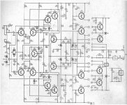
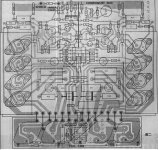
According to the amp circuit, if the original PCB condition is good, you can modify the amp to a modern amp as the last circuit by replacing all the new modern transistors and parts. You can use two pairs MJ15024/Mj15025 (250W Ic 16A each) high output power trnsistors.
I always mod the old amp with new parts and new circuit with the same old PCB. It will save time in design new PCB and the difficulty in heatsink and chassis mod works.
I always mod the old amp with new parts and new circuit with the same old PCB. It will save time in design new PCB and the difficulty in heatsink and chassis mod works.
Attachments
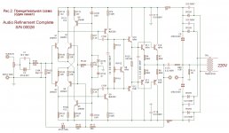
According to the amp circuit, if the original PCB condition is good, you can modify the amp to a modern amp as the last circuit by replacing all the new modern transistors and parts. You can use two pairs MJ15024/Mj15025 (250W Ic 16A each) high output power trnsistors.
I always mod the old amp with new parts and new circuit with the same old PCB. It will save time in design new PCB and the difficulty in heatsink and chassis mod works.
Thanks patrick - clearly you're familiar with the original Ampzilla circuit. Board is in pretty good shape other than showing its age. So I think you're suggesting that I modify the PCB per the new schematic on the right? An interesting idea. Is that something you have successfully done? Guess I'd need to see how many cuts/jumpers would be needed.
It would be a shame to ruin an original Ampzilla especially if it can be saved. Since there is only room for 2 pairs of output transistors per channel it would be risky to make a 200W amplifier using paralleled outputs. Most 200W amplifiers have 3 or 4 pairs at that voltage. I would love to have an original Ampzilla in my collection of GAS/SAE and SUMO. I have two Ampzilla IIa at the moment.
Craig
Craig
It would be a shame to ruin an original Ampzilla especially if it can be saved. Since there is only room for 2 pairs of output transistors per channel it would be risky to make a 200W amplifier using paralleled outputs. Most 200W amplifiers have 3 or 4 pairs at that voltage. I would love to have an original Ampzilla in my collection of GAS/SAE and SUMO. I have two Ampzilla IIa at the moment.
Craig
Yeah, when I posted right after it died in 2017, responses were bimodal - "you'd be stupid to rebuild that ancient SOA-deficient design" or "it's a classic and needs to be rebuilt." I lost interest and it has sat in my basement. I recently built a subwoofer for my basement system (wife has taken over my family room system with 24/7 CNN and Hallmark Channel) and am driving it with an amp channel from an old retired Denon rcvr, but am thinking a nicely rebuilt Ampzilla would be better, even though I really only need one channel.
I had to fix it back around 2000, so some of the power devices were replaced already, but are likely dead again. It has the nice double meter front panel. It is not in pristine shape having taken some dings over the years (at college with my son for a couple years), but not bad considering it is about 45 years old. I've made some mods over the years - added remote relay and replaced noisy AC fan with thermostatically controlled DC fan. The devices patrick mentions (MJ15024/15025 - 250V/250W) are more robust than the originals (140V/200W), and it certainly produced low distortion - I recall measuring 0.002% - the limit of my instruments back in 1975 after building it, so maybe I should think again of a rebuild. 😕
So I think you're suggesting that I modify the PCB per the new schematic on the right? An interesting idea. Is that something you have successfully done? Guess I'd need to see how many cuts/jumpers would be needed.
I have a few old amps, I will check their circuit and try to MOD them to improve their performance. Some good circuit amp just simple recap, replace modern parts like diodes,transistors,op-amp etc. Other simple designed amp I will rebuilt part of the circuit or even the whole amp circuit.
To do the mod, first step I will check the amp circuit and the PCB layout to make sure it has the potential to mod and fit the new circuit components, so that I've checked your amp circuit and the PCB layout and confirmed it can mod to the new schematic on the right.
If you like to mod the amp, I can help to study the PCB and make the mod changes like the cuts/jumpers would be needed, so that you can finish the mod in quick steps.
Each channel two pairs MJ15024/15025 (250V/16A/250W) working at +/- 69V DC is quite good enough for an amp, especially this amp has active fan cooling.
Ampzilla power supply is usually +/- 80VDC.
Craig
Yes, you are right - my diode bridge has also failed causing some bad readings. 80V it is. I did some quick calcs and it looks like with an 80V supply and an 8-ohm resistive load, I'd hit SOA with stacked MJ15024/MJ15025 around 100W, and at an even lower power level with paralleled devices. This is disappointing, but I guess not that surprising based on how many device pairs people use these days. It does make me question whether it is worth re-building.
I'm pretty sure my SOA calcs are NOT correct. Still have to figure out how to do that.......I did some quick calcs and it looks like with an 80V supply and an 8-ohm resistive load, I'd hit SOA with stacked MJ15024/MJ15025 around 100W, and at an even lower power level with paralleled devices....
I was wondering about that, I'm sure JB would not have designed it with such a low SOA. I know the original did have problems driving low impedance loads. The beta of the output transistors would drop and the drivers would go poof, that's the story I heard. The later Ampzilla II was supposed to have taken care of that problem but I think introduced different problems.
Craig
Craig
I don't believe SOA, which covers secondary breakdown, was "invented" until the late 70's, sometime after JB's Ampzilla design. I thought the calculation would be simple, but it is taking more research than I expected. I think the biggest issue is how reactive the speaker load can get. I've been looking at an article by Rod Elliot (SOA), and his standard procedure is to assume a 4-ohm speaker can go as low as 3-ohm with 45deg phase angle. That load does not look so good with Ampzilla, either stacked or paralleled, but consistently the stacked arrangement performs better. I just built a subwoofer and need to review it's impedance as that is likely the first speaker Ampzilla would drive. I think if I can convince myself I can re-build it into something reasonable powerful and reliable, I'll do it.
Found a relatively simple spreadsheet to determine SOA compliance - see "SOA Spreadsheet". Had to rewrite the equations to allow for stacked devices since it was written for parallel. Per Rod Elliot's suggestion, I used 6-ohm / 45deg for an 8-ohm load and 3-ohm / 45deg for a 4 ohm load, with +/- 80V supply and MJ15024 SOA. Pic below shows curves at 260W / 8-ohms and 310W / 4-ohm - right at the SOA limit. Paralleled devices performed more poorly. The analysis of course assumes perfect splitting of voltage between devices, so is best case, but overall I'm pleased that it looks as good as it does. We know the design is a bit weak, but maybe resurrecting the amp is warranted.
Attachments

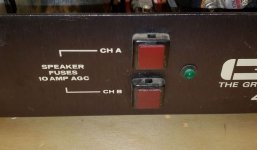
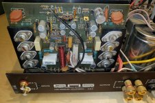
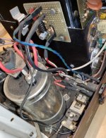
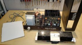
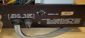
Thought I'd post a few pictures of the Ampzilla under question. First pic is all the pieces setting on my workbench, mechanics in mostly good shape - just a few scratches. 2nd pic shows added fan control bd on the side of the heat sink and remote turn-on relay at bottom of chassis. 3rd pic shows Ch-A amp bd, and 4th pic shows Ch-B amp bd (still with all its TO66's), as well as replaced speaker and RCA connectors. 5th pic shows replaced speaker fuse holders - one of the originals broke so I replaced both. You can also see the added green LED which comes on when the fan is active. 6th pic shows serial number - you can also see the added input connector for the relay. Just noticed the warning - DO NOT REMOVE COVERS - NO USER SERVICEABLE PARTS INSIDE!!! 🙂
Attachments

Idea
There is a figure 6.21 L-Mosfet high power amp designed by G.Randy Slone in "The Audiophiles Project Sourcebook" capable of 200W/8R with 2 pairs of 2SK1058/2SJ162. By modifying these with BUZ 901 CDP / BUZ 905 DP, it can withstand up to 85Vdc for power output of 400W/8R.
The pcb from book measures 9.27" by 4.43". I believe it can be modified further for better fit.
I see your main problem, your workbench is far too clean! 😉
Craig
I spent the entire morning cleaning it off so I could take the pics and not embarrass myself! I'm actually more of a hobbyist woodworker, but spent 40 years as a EE development engineer for public safety communications equipment, so also enjoy electronics. Been retired about 5 years.
There is a figure 6.21 L-Mosfet high power amp designed by G.Randy Slone in "The Audiophiles Project Sourcebook" capable of 200W/8R with 2 pairs of 2SK1058/2SJ162. By modifying these with BUZ 901 CDP / BUZ 905 DP, it can withstand up to 85Vdc for power output of 400W/8R.
The pcb from book measures 9.27" by 4.43". I believe it can be modified further for better fit.
Thanks. I'll see if I can hunt down the book, although right now I'm leaning towards a "simple" rebuild.
First, find a source of those lateral type mosfets, if that's the way you choose to go. In recent times, they seem to have become difficult to find at all in the US. Similar Exicon and Semelab?? branded types from Profusion PLC in the UK are still available but freight costs may be significant.
- Home
- Amplifiers
- Solid State
- Amp board to work in old chassis