...Apologies to OP for going off thread.............😉
No worries, I occasionally play with heavy bassbins at free parties and I always "forget" my earplugs 😱
I'm afraid I just like loud music....
Back on topic;
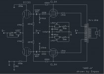
I just installed two resistors at the cathodes as Revintage suggested. Didn't have any 250ohm resistors so I fitted 270....
I cannot claim I have "golden ears" (see above) but it seems Louis' trumpet has got a smoother edge. 🙄
Attachments
Hi Empee,
The RH84se schematic called for a 5k output transformer. In the spirit of doubling two se amps is that how you decided on 10k for the pp output transformer or did you have other reasons for this choice.
Just curious
Brgds Bill
P.S. Like the white spots that have just appeared on that wonderfully black velvet background.......🙂
I'm still building the quietest amp ever. Once its finished, I hope to have fixed that.
Or drop it on one's foot.
Hey Empee,
Glad you liked it. Have simmed it and when comparing THD, it should be 50% lower with the resistors in place.
If, in the next step, substituting the 12AT7 with depletion MOSFET DN2540, THD will be reduced tenfold!
Glad you liked it. Have simmed it and when comparing THD, it should be 50% lower with the resistors in place.
If, in the next step, substituting the 12AT7 with depletion MOSFET DN2540, THD will be reduced tenfold!
...is that how you decided on 10k for the pp output transformer or did you have other reasons for this choice...?
The Philips EL84 datasheet calls for 8K, but I had a 10K OPT so that's why I used it. From what I learned on DIYaudio,
is using a higher impedance OPT reduces distortion at the expense of output power (and some bandwidth, too).
<edit> I see the OPT I used has an Ra-a of 9K (found a datasheet)
Revintage;
did you sim the complete amplifier ? I'm curious what those sims look like !
Can you give us some numbers ? (Pout / THD)
What program do you use for simulations ?
I really like to get into simulation programs but I do not know that much about software. Do you have a tip on where to look in the internet ?
Cheers,
Empee
LTSpice. You get 12AT7 and DN2540 at the same sheet for comparision. pentode output. Can also do UL.
As your amp is stricly Class-A 10k will suit you fine. For stability reasons I would run it pentode. Try and listen. Just go for 100ohm on each Sg-socket to a common 1k and then to B+. Also try adding adding a 47u cap to ground at the junction point of the three. But the cap is probably not needed.
As your amp is stricly Class-A 10k will suit you fine. For stability reasons I would run it pentode. Try and listen. Just go for 100ohm on each Sg-socket to a common 1k and then to B+. Also try adding adding a 47u cap to ground at the junction point of the three. But the cap is probably not needed.
Last edited:
For stability reasons I would run it pentode
I do not understand; can using ultra linear taps make an amplifier instable ?
Too bad my amplifier isn't exacly build as to easily change the screengrid resistors.
Easiest way to try pentode is to disconnect the wires on the UL taps and place them at the centretap, at B+.
Would the 1,5K resistor be an acceptable value ?
Last edited:
Using UL taps can sometimes make the output stage unstable. At frequencies typically around a few hundred kHz the screen taps can give positive feedback instead of negative feedback. The output stage then becomes a power RF oscillator. The solution if this occurs is either a better quality transformer, or snubbers.
In a proberly designed Schade UL is unnecesary. The Schade in itself makes the pentode act like a triode but with the efficency of a pentode. So skip the taps altogether as they, as I and also DF96 says, often causes stability-problems.
So-called Schade feedback doesn't really make a pentode act like a triode, although it does reduce the effective anode impedance. It is simply an anode follower circuit, but using the non-linear output impedance of the driver stage as the input resistor. It reduces output distortion at the expense of increasing driver distortion. On balance this can be a worthwhile exchange, provided the transconductance of the driver stage does not vary much with signal or varies in a way which offsets the change in the output stage.
Hey DF96,
If you want to complicate things for the not so initiated member, as Empee gives an impression to be, you are off course correct. This has already been explained in numerous threads at this forum.
But if we look at it pragmately, the end-result is as I explained. Also soundwise the Schade come close to triode.
no, no, please give me the full information !!
If I do not understand I'll say so or have another search query on my hands,
but in the end it's really a learning experience.
So please, do not refrain from real information from which I can learn 🙂
Thank you very much for all the information so far,
I will try the pentode connection as soon as I find the time...
Can you give me some information of the value of the screengrid resistor and
what it does to the sound ?
I read a lot of guitar amps use this resistor as to 'tune' the sound.
So what is best for hifi ? lower or higher values ?
Glad to see your curiousity is there🙂. If you are interested I suggest you search the forum for Schade to get an even deeper insight in the subject both in theory and practice. Begin to search for the original paper(1938?).
EDIT: Found it, check the end of the document.
http://www.tubebooks.org/tubedata/beam_power_tubes.pdf
EDIT: Found it, check the end of the document.
http://www.tubebooks.org/tubedata/beam_power_tubes.pdf
Last edited:
If it were SE Pentode driving SE Pentode w plate to plate feedback, yes it does make a triode.
Schade proved this feedback (if not internally blocked by a screen) is what makes Mu in real triodes in the first place.
He simply replaces the missing feedback externally, and connect the dots. Fig 35!
The only thing not "triode" here, is that feedback from push and pull are blended...
I don't think that disqualifies it a triode any more than a pair of push pull
triodes with transformer coupled plate and CCS coupled cathode voltages.
They suffer exact same blending of feedbacks to no untriodeworthy harm.
Triode driving Pentode w. plate to plate feedback is possibly not a Triode overall.
Depends how constant is driving triode plate resistance and Gm? Mu here fights
against both of these and requires more cathode resistance for the driver...
With high enough unbypassed cathode resistance, its probablt legit.
The effect of screen currents into UL taps has no place in this model.
That much maybe isn't Triode, then again maybe its just a smaller triode
of different Mu in parallel with the larger Schaded model.
Attachments

Last edited:
I am not convinced. The internal feedback from the anode in a real triode has the same 3/2 law as the grid, so the two distortions cancel (in the ideal case). Resistive feedback does not give distortion cancellation, but distortion reduction. I accept that there may be some distortion cancellation from the characteristic of the driver, but this requires a careful balancing which is unlikely to survive valve ageing etc. The graph you give shows a reduced anode impedance, as you would expect from negative feedback, but not triode-like linearity.
As I said, Schade is essentially an anode follower, but with the added complication that the input resistor is non-linear. I suspect the reason people get excited about it is that they associate triodes with low distortion, forgetting that this is only true for a high impedance load (i.e. not an output stage!).
As I said, Schade is essentially an anode follower, but with the added complication that the input resistor is non-linear. I suspect the reason people get excited about it is that they associate triodes with low distortion, forgetting that this is only true for a high impedance load (i.e. not an output stage!).
Hi !
Loads of thing happening at the same time here;
First;
I connected the amps in Pentode. Just took the wires from the UL taps
and connected them to B+. Didn't change the 1K5 screen grid resistor.
It does have slightly higher output power.
When I fed a mono-signal (Y-split wire) on one pentode and one UL monoamp
I found the centre of the music shifted towards the pentode amp.
Switched left/right speakercable and the centre was on the other side of the middle...
Second;
I downloaded B2spice as I found it has most tubes allready in the library.
Still going trough the tutorial....
Third;
I read (most of) the posts about Shade feedback, and like DF96 said in this thread,
a triode pre stage will have high distortion because of a too low impedance load
of the output stage.
Too bad, because I got two PPP EL34 monoblocks, and up until this thread I wanted
to double the RH34 and parallel the output stage. but doubling the output tubes
would make the impedance even lower !
What do you suggest to do;
Forget Shade feedback alltogether or should I go for a different driver in a PPP EL34 ?
Maybe a third, middle stage ? (CCS'ed LTP -> Shade'd pentode drivers -> PPP EL34)
Cheers,
Empee
Lets not panic about the triodes in the driver stage.
Instead lets clarify some facts about Schade, Triodes, and Mu.
Schade can work just fine with any driving impedance high medium or low.
In the case of low, you just add a resistor in series. But the point is that
the driving impedance appear resistive and CONSTANT over the voltage
range where feedback linearity is beneficial. Because any resistive leak
at the driving plate will become part of the feedback divider, the other
dividing values may have to be adjusted.
Now, absolute linearity is not necessarily a good thing when we approach
either rail where clipping will occur. A soft clip is preferable. If the plate Z
of a driving triode varies only near the rails, it could be more of a feature
than a problem.
The grid of a triode is not the control surface, the control surface is an
entire capacitive field. Yes we are INSIDE a capacitor. The voltage divider
that creates Mu is a capacitive divider. Somewhere inside that field is a
pivot point for Mu where feedforward from the grid and feedback from the
plate cancel. Then x^(3/2) law for Gm applies from this pivot point. I do
not buy theory that an external resistive divider simulating this field will
somehow avoid or unbalance 3/2 law once its applied to a real grid.
Anyways, two things cause plate impedance to be non-linear. And 3/2
law is only one such law. The other is that a triode is many parallel
triode paths. Not all paths created equal do not cut off simultaneously.
Gm varies much more than x^(3/2) when we approach cutoff. Not a
problem, maybe a feature, just know its there when driving Schade.
Oddly enough, the final resulting Schaded output Pentode has much
the same 2/3 law and multipath cutoff as a triode, even if no triodes
are used in its creation.
The real deal is simply about simulating that internal field externally
with minimal phase shift. Preferably direct coupled. Unfortunately I've
not found any convenient external method to direct couple a plate
feedback to the grid. At least one cap always seems necessary, so
the simulation of that field will always be RC delayed in time. You can
direct couple plate feedback to the cathode by abusing a PNP, but
that actually makes Schaded anti-triode. Whole 'nother chapter.
Last edited:
An ideal triode operating under ideal conditions (e.g. infinite load impedance) has constant mu and zero distortion. The whole point about triodes is the distortion cancellation - this is feedback, but quite different from linear feedback. An ideal pentode operating under anode follower feedback (i.e. 'Schade') will have an infinite number of distortion components, as the 3/2 law output components will be mixed back with themselves. This is simple mathematical fact - use the feedback equation. Pentode+Schade does not equal Triode.
I assume that a 'capacitive' field is the same thing as an electric field? I accept that real valves are more complicated than ideal valves, but if a theory is wrong in the ideal situation then it is also wrong elsewhere.
I don't want to say any more, as I will simply be repeating myself and I don't want to hijack the thread.
- Status
- Not open for further replies.
- Home
- Amplifiers
- Tubes / Valves
- Amp-A, a variation to the EL84 Push Pull theme