I checked with a 50 hz sine wave from a head unit full volume and didn't really see any signal. But will re check again
I checked the 4 driver ic's and got these readings.
1
1.....32.04k
2.....36.00k
3.....04.31k
4.....0.916m
5.....32.60k
6.....32.57k
2
1...32.25
2...36.20
3...04.30k
4...1.005m
5...32.60
6...18.5m (need to double-check)
3
1...32.20k
2...35.50k
3...04.32k
4...247.1k
5...32.60k
6...1.900m
4
1...32.20k
2...35.75k
3...04.34k
4...0.990m
5...32.65k
6...1.800m
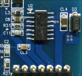
I apologize. I forgot to add the designations for the IC's
1...U-1
2...U-5. Double checked step 6 I got 2.300 m ohms
3...U7. Double checked step 4 I got 2.000 m ohms
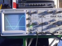
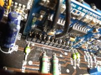
With 12v on B+ and no remote power applied and using a 50hz sine wave.
I've got this on the scope. (See pic) scope set to 2 ms/div. 5 volts/div
I've learned from this. (Correct me if I'm wrong please)
If I have 5 volts DC between pads 1 & 3 of the low side fets.
Then I should have my volts/div set to 5 on my oscilloscope?
1...U-1
2...U-5. Double checked step 6 I got 2.300 m ohms
3...U7. Double checked step 4 I got 2.000 m ohms
With 12v on B+ and no remote power applied and using a 50hz sine wave.
I've got this on the scope. (See pic) scope set to 2 ms/div. 5 volts/div
I've learned from this. (Correct me if I'm wrong please)
If I have 5 volts DC between pads 1 & 3 of the low side fets.
Then I should have my volts/div set to 5 on my oscilloscope?
Attachments
What point were you probing for the sine wave?
Was the probe set to 1x or10x for each waveform?
What is the rail voltage?
Was the probe set to 1x or10x for each waveform?
What is the rail voltage?
I have an RCA B and C adapter I used in channel 2 of the scope plugged into the RCA out of the amp.
Channel 1 square wave was probbed to a gate pad of a low side output
At 11.9 volts and 3 amp draw rail voltage was 115.4 DC red probe at drain. Black probe on source ( if I remember correctly)
Channel 1 square wave was probbed to a gate pad of a low side output
At 11.9 volts and 3 amp draw rail voltage was 115.4 DC red probe at drain. Black probe on source ( if I remember correctly)
When searching for threads, did you see the ones using a 9v battery for the high-side supply?
Or the ones using low-voltage via added windings on the transformer to eliminate some of the risk for the outputs?
Or the ones using low-voltage via added windings on the transformer to eliminate some of the risk for the outputs?
The 9v battery is connected across the high-side supply filter cap (CL1, etc) to allow the high-side to produce a drive signal.
Using a low voltage supply limits the energy stored in the rail caps and can help protect the output FETs, when you finally install them.
4000.1
As a side note, slide the power supply board into the heatsink (if you haven't already) to be sure that they're OK on installed height. In some amps, factory height is the absolute maximum. It's better to know if the height is OK before installing the output transistors.
I haven't tried putting it into the heatsink yet. HOPEFULLY it will go. I'll try it tomorrow when I get off work.
I found and read that 4000.1 post you linked the other night. And just read it again. I was unsure of (myself) adding the windings and going that route. Although if it was my own amp I would have tried it with no worries lol
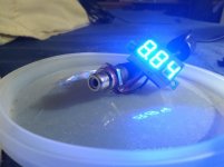
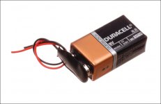
But If it will work. I put this together to use for 9v test. As long as it's (Perry Approved)
I found and read that 4000.1 post you linked the other night. And just read it again. I was unsure of (myself) adding the windings and going that route. Although if it was my own amp I would have tried it with no worries lol
But If it will work. I put this together to use for 9v test. As long as it's (Perry Approved)
Attachments

I'll check it that way.
I don't have an adjustable power supply for lower voltages. (converted PC PSU) I noticed I had an old Sony PlayStation power supply laying around taking up space so I just added a female RCA to the end of it and made a pigtail with a male RCA.
For some reason the picture didn't upload to show what it was
Attachments
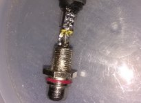
That may work but if you have rail voltage, the isolation internally must be able to withstand that voltage. The 9v battery is safe.
One thing I've never checked is whether the case of the 9v battery is connected to the negative terminal. If it is, the case of the battery would need to be insulated.
One thing I've never checked is whether the case of the 9v battery is connected to the negative terminal. If it is, the case of the battery would need to be insulated.
Ok, I'll be sure to verify before hand.
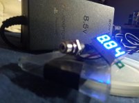
Just to be sure. I'm powering the amp as before. But now with the 9v battery added
Just to be sure. I'm powering the amp as before. But now with the 9v battery added
Yes. The battery should not get hot or warm. If it does, shut the amp down and disconnect the battery (cut one of the battery wires). I've never had any problems using a 9v battery. This is just an FYI.
The high-side should produce a drive signal similar to the low-side. If you can't see a stable waveform, connect a load across the speaker terminals. You can even just connect a jumper between them if there are no outputs in the amp.
The high-side should produce a drive signal similar to the low-side. If you can't see a stable waveform, connect a load across the speaker terminals. You can even just connect a jumper between them if there are no outputs in the amp.
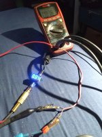
Well..... With 12v at B+ terminal, remote on , 9v battery attached to filter cap. 50 hz sine wave
Initially had a drive signal hovering it seems just above ground. And then it stopped. At the time it stopped I caught a little cloud out of the corner of my eye. But unsure of where it came from.
Power light still lights up green. Nothing got hot. When I noticed. I felt the chip. It wasn't hot either.
I'm hoping it's just paranoia.
Attachments
No. What happens is that the high-side floats up so you may not be able to see a drive signal with a scope. Connecting across the speaker terminals prevents it from floating.
I removed the 9v battery connector and re-done the 6 step check.
1...37.43k
2....36.40k
3...04.31
4...32.20
5...31.85
6...reads dead short. Is it possible I popped the filter cap?
1...37.43k
2....36.40k
3...04.31
4...32.20
5...31.85
6...reads dead short. Is it possible I popped the filter cap?
Not likely. The IC would be the weak point. Did you possibly connect the battery reversed?
Are 3, 4 and 5 ohms or k ohms?
Are 3, 4 and 5 ohms or k ohms?
- Status
- Not open for further replies.
- Home
- General Interest
- Car Audio
- American Bass VFL audio 8k power supply failure