Thank you. The correct ones have been ordered.
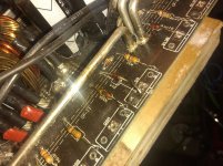
They are connected to the drain legs of the power transistors. Would it be ok to test without them?
Also the pwm driver board has a KA7500C chip. There isn't much info here for them. Is the pinout the same as the 494?
They are connected to the drain legs of the power transistors. Would it be ok to test without them?
Also the pwm driver board has a KA7500C chip. There isn't much info here for them. Is the pinout the same as the 494?
Thank you.
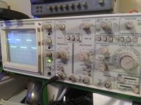
I haven't checked the chip yet. I've replaced all the gate resistors. All gets from the amp are removed. With power applied. Negative probe on main ground. All gate pads show 3.8v and (I think) according to my new old scope they all have a clean signal
I hope this would mean all is well in the gate drive circuit. I can't find my needle probes to check the chip safely
Attachments
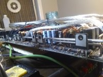
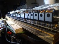
I installed 2 fets per bank for a total of 12 for testing. On a current limiter none of them warmed up out of the sync.
After reading your oscilloscope page on basic car audio site.
Could you confirm a good drive waveform or explain what you see happening? My volts/div .5 and time/div 10us
After reading your oscilloscope page on basic car audio site.
Could you confirm a good drive waveform or explain what you see happening? My volts/div .5 and time/div 10us
Attachments
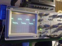
What are you using for a probe? The waveform would look right if you were using a 10x probe.
If you touch the probe to the B+ terminal, does it deflect to just over the top of this waveform?
Is the height of the installed PS FETs the correct height?
If you touch the probe to the B+ terminal, does it deflect to just over the top of this waveform?
Is the height of the installed PS FETs the correct height?
I am using a 10x probe. I'm not sure about touching the B+ Terminal yet. I will have to check. The waveform is of the gate pads. 3.8v
The height of the fets I believe is correct. I removed the test fets and used a gauge to get them all lined up. But not 100% sure if they are correct height. I haven't applied power since I installed all the fets. The rectifiers are still out of the board. I'll check the B+ to be just above the waveform I had earlier
The height of the fets I believe is correct. I removed the test fets and used a gauge to get them all lined up. But not 100% sure if they are correct height. I haven't applied power since I installed all the fets. The rectifiers are still out of the board. I'll check the B+ to be just above the waveform I had earlier
Attachments
If you're using a 10x probe, the waveforms look OK. I've never seen a 10x probe with that small of a connector at the scope.
OK on the height. The parts were at different heights in a previous photo. Also, when mounted closer to the board (less lead length), it's important to get them installed where they will lay perfectly flat. Yours look close enough for the longer leads.
OK on the height. The parts were at different heights in a previous photo. Also, when mounted closer to the board (less lead length), it's important to get them installed where they will lay perfectly flat. Yours look close enough for the longer leads.
I am probably the thickness of the board taller than the original fets.
And yes B+ when touched it just over the waveform.
I must say it's ALOT less stressful not having to worry about smoke clouds (for the most part) with the scope.
And yes B+ when touched it just over the waveform.
I must say it's ALOT less stressful not having to worry about smoke clouds (for the most part) with the scope.
Attachments
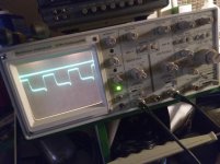

Touching to B+ and seeing that amount of deflection is a quick way to confirm that you're scope is set correctly for reading PS drive signals.
Made a little progress today. Got the rectifiers installed. Double checked all solder joints.
Gate pads on power fets still at 3.9v w/ good waveform
Center leg at 12v
Rail voltage + & - 121.4v
Draws 14 amps upon startup then mellows out at 2.6 amps at idle
So far so good,
Gate pads on power fets still at 3.9v w/ good waveform
Center leg at 12v
Rail voltage + & - 121.4v
Draws 14 amps upon startup then mellows out at 2.6 amps at idle
So far so good,
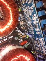
I've been rummaging around about the IRS21844S chips & have attempted to check for failed chips while the driver board is still installed BUT my hot dog fingers and eye squints are not in sync tonight.
Could you please advise me on what voltages and wave forms I should be seeing on the pads of the output transistors before they are installed (assuming everything is running as it should) ? Just trying to prevent myself from feeling like I'm on am episode of ghost hunters 🙂
Reason I ask is tonight I found this quote.
And last night while triple checking for anything obvious. I found this BUT I "fixed" it
Attachments
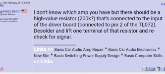
Instead of posting a screen-cap, right-click the link in the right-hand side of the post (#..) and copy/paste that link. That allows the reader to see all corresponding posts.
If you drive a strong signal into the amp (50-100Hz), do you see any signal on the low-side FETs?
There is a lot to know about testing these and it's been covered a lot. Do an an advanced search of the car audio forum for posts by me and with the key word 21844. Read for at least 30 minutes, paying special attention to the posts mentioning 10k resistors and shorting between pins 2 and 3 of the 21844.
- Status
- Not open for further replies.
- Home
- General Interest
- Car Audio
- American Bass VFL audio 8k power supply failure