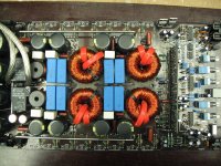
I have an AB 500.1 here. It had shorted outputs and power supply. I replaced all the drivers (were A1275/C3228, used BD139/140). Replaced all the IRFP064N's. Put in the outputs but left the rebuilt card out till I tested the amp.
When I apply power and ground there is no current draw. As soon as I apply remote power there is huge draw on the 2ohm 50watt resistor. Power drops from 13.54v to 8.3ish vdc. The resistor gets hot to touch in a couple minutes. None of the ps transistors get hot at all.
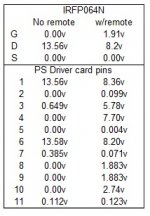
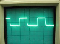
I have a nice square wave on the gate (only2v though, I assume due to the power drop. B+ voltage on the drain (which drops to 8.2v with remote power applied), and 0v (ground) on the source.
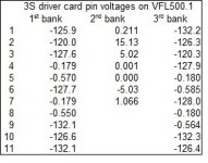
Please see attached pics for wave form and power chart for the ps driver card pins.
When I checked D3A (ps driver card, removed from the amp) on diode check I get .977v one way and .137v the other direction.... is that normal with this card? I have an older version card that doesn't even have a D3a on it, so I can't check.
Any idea why its drawing so much current?
When I apply power and ground there is no current draw. As soon as I apply remote power there is huge draw on the 2ohm 50watt resistor. Power drops from 13.54v to 8.3ish vdc. The resistor gets hot to touch in a couple minutes. None of the ps transistors get hot at all.
I have a nice square wave on the gate (only2v though, I assume due to the power drop. B+ voltage on the drain (which drops to 8.2v with remote power applied), and 0v (ground) on the source.
Please see attached pics for wave form and power chart for the ps driver card pins.
When I checked D3A (ps driver card, removed from the amp) on diode check I get .977v one way and .137v the other direction.... is that normal with this card? I have an older version card that doesn't even have a D3a on it, so I can't check.
Any idea why its drawing so much current?
Attachments

Last edited:
There's a few things I can suggest but Perry will have more insight.
You really should of checked drive signals on pwr FETs prior to installing them.
These amps draw alot of current on start up.Once you get the rail caps charged its not as bad.
Do you have a fairly large power supply? 30 amps +?
Some larger amps won't start with a current limiter in line.
I generally use a 15 amp inline fuse and closely watch the ammeter on my power supply.
What was the scope setting for the drive waveform?
It seems to be hanging a little above ground on the falling edge.
It seems to be hanging a little above ground on the falling edge.
yes, it does seem to jump up on the wave form. I have a 90 amp Cadence ps connected to 2 group 31 AGM batts.... sooooo ya... current supplied. 🙂
I'm not a super expert but I would of personally checked pwr supply gate drive signals before installing the MOSFETs let alone outputs.
I'm a little stuck on advise not knowing the scope settings.
If you not pulling almost to ground on gate drive signal and its not 10v approx of amplitude then your going to have problems.
I'm assuming the outputs have pulldown resistors.?
If you have the outputs installed and they don't have pull downs or the pull downs are blown.Then,that's another issue that will draw excessive current.
The output card is not installed... therefore the outputs are isolated. I'll pull the rectifiers just to be sure but ya... no voltage is being made, and the relays do click on. However no power or protect lights.
I'd have to wire it back up to double check the scope settings.
I'd have to wire it back up to double check the scope settings.
O.K. A little update... problem was not the ps... powers up fine after pulling the rectifiers. Pulled all the new outputs back out and found 2 shorted ones... all legs shorted, but still looks good as new. 🙁 SO, reinstalled all the outputs and replaced the 2. Amp turns on using power limiter, relays release muting, and I have a clicking noise coming from around the output filter inductors, and between -1.24 and -2.5v dc pulsing on the output terminals.
I did check output driver IC's (that I also replaced) and they seem to be testing fine.
I did check output driver IC's (that I also replaced) and they seem to be testing fine.
Is there a reason you have the outputs installed without the driver card?
Its likely clicking because it can't start up due to current limiter and or something in output section causing excessive current draw.
You need to install card and remove outputs.
Does this have the driver card with 4 ir21844s?
Its likely clicking because it can't start up due to current limiter and or something in output section causing excessive current draw.
You need to install card and remove outputs.
Does this have the driver card with 4 ir21844s?
the card is installed and its making this clicking. Yes its the 3S driver card with the 4 21844s. The amp is on and not in protect, even with the current limiter. Relays release muting. If I try to power it up without, it makes a much more louder arcing sound and makes my 30amp breaker kick in and out.
I'll pull all the outputs shortly
I'll pull all the outputs shortly
Last edited:

You need to remove outputs .
Confirm you don't have any shorted driver ic's.
Checked square wave on one of the center pins on driver board.Can't remember which one.
Perhaps even check square wave on pin one of ir21844
The low side drive will be present but the high side won't.
You'll need to connect a 9 volt battery across the 4 smd caps beneath the driver ic's.
Polarity is important.I can't remember off hand where the positive and negative go.
I'll have to check this evening when I'm home.
Connecting a battery will let you see the high side drive.
I removed the outputs and the clicking sound stopped. It was coming from one of the small inductors.
Here are the voltages I get from the card. Also I didn't see any square wave on any of the center pins.
I have the following voltages on the output transistor pads
G) -0.561
D) 132.6
S) -0.180
G) -128.1
D) -0.180
S) -132.5
Here are the voltages I get from the card. Also I didn't see any square wave on any of the center pins.
I have the following voltages on the output transistor pads
G) -0.561
D) 132.6
S) -0.180
G) -128.1
D) -0.180
S) -132.5
Attachments
Last edited:
Did you confirm that you don't have any leaky or shorted drive sections on any of the driver ICs? Many times the driver ICs are damaged when installed.
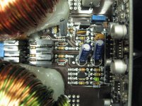
I went over all 4 IC's and the readings all match. However... I don't recall on previous cards having a reading between B6 to R7. Please see attached photo. Would something else cause this or could all 4 be damaged? (R=red probe, B= black probe orientations) This is the first time I've bought these in a cut tape strip... I usually buy them in the hard plastic tube. Not sure if it makes much difference.
Attachments
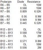
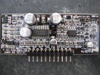
I checked another card... and it seems to read OL from B6 to R7. Also another new IC reads OL out of the circuit... so, I'm going to replace all 4 driver IC's again and see what happens. I know there was 2 shorted (all 3 pins but were new transistors?!?) outputs, however not sure from exactly which bank.
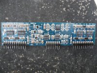
Hopefully its nothing external and it just happens again to the new ones Here is a pic of the actual card. I did also replace U3 and U4...
Hopefully its nothing external and it just happens again to the new ones Here is a pic of the actual card. I did also replace U3 and U4...
Attachments
Last edited:
I removed the IC's and all of them test O.K. between pins 6 and 7 now. 🙁 SO, going to install new ones anyway and see what happens.
I replaced all the 21844s and back to the same point. On diode check I have .948v with the black probe on pin 6 and the red probe on pin 7... As soon as I soldered each one it changed. I'm quite positive I'm not damaging them. I've installed many of them, never had all 4 fail. And the 4 I removed tested fine out of the circuit. What else could cause this reading between those pins. I checked just the pads and it was OL before I added the IC.
I'm stumped...
I'm stumped...
Last edited:
Read it on ohms. On diode check, you may simply be reaching the breakdown voltage os some semiconductor on the board. Reverse the probes and compare resistance with both probe configurations.
- Status
- Not open for further replies.
- Home
- General Interest
- Car Audio
- American Bass VFL 500.1