What would cause these 0.1uf caps to burn like this ?
Also when this amp is hooked up in the vehicle it burns the ground shields inside the head unit
I tested for voltage on the rca shield grounds of the amp and get no voltage
Also when this amp is hooked up in the vehicle it burns the ground shields inside the head unit
I tested for voltage on the rca shield grounds of the amp and get no voltage
Look at the RCA shields and the non-active speaker terminal with your scope. Do you see a clean ground (no high-frequency waveforms, no DC)?
I will have to get back to you later tonight or tomorrow to check to see if I get a clean ground and no dc .
I’m removing the power supply fets right now and cleaning the board since this was someone else’s repair at some point in time and the did a horrible job at soldering .
I’m removing the power supply fets right now and cleaning the board since this was someone else’s repair at some point in time and the did a horrible job at soldering .
Back to this amp . I fixed the solder issue on the power supply fets .
Can I remove the audio driver board to check to see if I get any dc on the shield grounds of the rcas and check for clean ground and no high frequencies?
Can I remove the audio driver board to check to see if I get any dc on the shield grounds of the rcas and check for clean ground and no high frequencies?
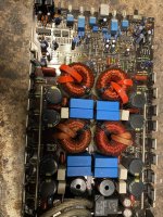
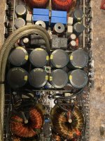
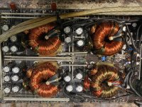
Here are some photos of the board .
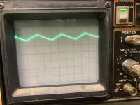
Also here is the drive on 2 banks of fets . Something isn’t correct since it looks like the bottom of the waveform is not being pulled back to ground .
Any ideas what might cause this ?
Scope set to 5us 2volts/div
The trace was centered on the reference line before looking at the drive
Also here is the drive on 2 banks of fets . Something isn’t correct since it looks like the bottom of the waveform is not being pulled back to ground .
Any ideas what might cause this ?
Scope set to 5us 2volts/div
The trace was centered on the reference line before looking at the drive
Attachments
Is this a power supply waveform?
I'm assuming that the photo is the current condition of the amp since you didn't indicate otherwise.
I'm assuming that the photo is the current condition of the amp since you didn't indicate otherwise.
Follow the drive from the driver IC output towards the FETs. Where does the signal become distorted?
I have good drive on 1 side of the gate resistors but not the other side . I will have to check further back since the amp will draw excessive current with the fets installed
I don't know a lot about diagnosing bad boards but I know that what I'm looking at has likely more then one problem and a few more ready to happen once the current problems are fixed. That board looks worse then the old Hiphonics boards of the late 80's early 90's. Decent designs but no QC. But this board doesn't even look like a good design. Those transformers are a likely problem, especially on the output side. I bet there is a short in one of them. Do they move around on the board? They aren't held down for beans and by looking at the pics this board doesn't even have any support for the center of the board anywhere near those heavy components. That thing is flexing and vibrating all over the place and that hot melt glue they set the transformers in is not likely doing much. Plus it looks like there is a lot of bad soldering going on on that board. Those no name 85 degree caps that are surrounded by heat sources are likely put well above 85 degrees during hard operation. They have a bank of FETS on one side and transformers on the other side and that 85 degree rating is to low. I bet the specs on those caps shift when in hard use. If you ask me that amp isn't even worth fixing.
Back to this amp .
I have good drive signal on pins 9/10 of the 494
I also have the same drive signal on 1 side of the gate resistors .
When I touch the gate pad for the fet that’s where the signal is messed up .
Any ideas what might cause this
I have good drive signal on pins 9/10 of the 494
I also have the same drive signal on 1 side of the gate resistors .
When I touch the gate pad for the fet that’s where the signal is messed up .
Any ideas what might cause this

Are you saying that when you have the signal above on the gate side of the gate resistor, you have a perfect square wave driving from ground to 12v on the other side of that same gate resistor?
Without the loading capacitor, do you have a perfect square wave on both sides of the gate resistor and the gate pad?
Do you see the same thing (triangle waveform) on all FET gates?
Do you see the same thing (triangle waveform) on all FET gates?
Without a loading cap I get good drive signal on all of the gate pads for the fets .
With a loading cap I get the same triangle wave on all of the gate pads . With it removed I get a good squarewave signal on all of the gate pads . Both sides of the resistor .
The issue is the amp will draw excessive current with the fets installed
With a loading cap I get the same triangle wave on all of the gate pads . With it removed I get a good squarewave signal on all of the gate pads . Both sides of the resistor .
The issue is the amp will draw excessive current with the fets installed
I guess I’m an idiot didn’t catch it til just now . When I bought the resistors the bag said 47ohm 1% the resistors are actually 470 ohm
- Home
- General Interest
- Car Audio
- American Bass 500.1