It basically failed soon as rail voltage raised high enough. I kept tapping the remote on... watched the rail rise, relays clicked on, clicked off... went into protect. I reset protect. Jig light illuminated and the power and protect lights went out. The power supply shut completely off.
U1 had a damaged low side drive. So I removed them all, and replaced them. Cause all 4 low side transistors I had in (one per bank) were shorted.
U1 had a damaged low side drive. So I removed them all, and replaced them. Cause all 4 low side transistors I had in (one per bank) were shorted.
Is there any problem with the 12v low side regulator? Could the voltage be spiking due to some short bypassing the regulator or otherwise getting more than 12v across the low side of the ICs?
If you have to replace the ICs again. I'd suggest installing only one IC on the driver board at a time to see if it fails. Install U1 last.
If you have to replace the ICs again. I'd suggest installing only one IC on the driver board at a time to see if it fails. Install U1 last.
Possibly. I'll go over them again. I did have right about 12v when checking them from ground pin to output pin. There are 2 7812's in these amps. I'll go over them again first before anything else once I get it back up on the bench. Hell I have many new ones... I'll just change them completely, but would be nice to actually notice the problem. Thanks Perry.
I'll do the IC thing too if need be. Could I just bridge pins 2 and 3 of each and just unsolder one bridge at a time? Would that be the same? Or if there are spikes it could still get damaged?
I'll do the IC thing too if need be. Could I just bridge pins 2 and 3 of each and just unsolder one bridge at a time? Would that be the same? Or if there are spikes it could still get damaged?
Sorry... that would be fed to pin 7 on the IC. If I lift pin 7 (to isolate), and bridge 2-3. That should work? Then release one at a time?
I don't have any headers, and not very good at replacing these in the amp. So, I'm trying to remove the card as little as possible... although I've gotten to be pretty good at it, lol.
I don't have any headers, and not very good at replacing these in the amp. So, I'm trying to remove the card as little as possible... although I've gotten to be pretty good at it, lol.
Last edited:
Sooo... seems like 12 wraps, 50v, things were good... much over that, something is acting up. Sometimes the jig light would illuminate, sometimes not, but the jig wouldn't make much power (1.5v or so) and the ps transistors got warm fast. My bench supply dropped from 12v to about 8ish and current stayed maxed out at the 4amps I set it to. It usually does that till caps charge then stabilizes. Not in this case.
I also noticed -1.050+vdc on the output terminals.
Brought it back down to +/- 50v and it acted up still on the first and second attempts... now seems fine again.
I'll play more in the morning. But seems like whatever it is, isn't liking over 50v. And I did check the 12v regulators. They seemed fine, but I replaced them anyways. Still having problems.
Also, I have some 24n40F's in the outputs. So, the old 064N isn't the issue.
Only having about an hour a day to work on this amp sucks, lol.
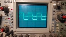
OK, I have installed one set of rectifiers. Output section is getting full rail voltage. 3 of the 4 banks will power up and make a decent square wave. They do get hot rather fast, but there is only one per bank.
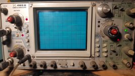
The 4th bank, will give green light. Relays click on, there is 1-1.8vdc on the output terminals and I can hear a ticking sound coming from somewhere. No wave is forming on that bank. Trace just sort of jumps a couple hairs up and back down with the ticking.
I have to get ready for work. So, I'll look more into this section tomorrow. Oh, and I now have 2 sets of probes.")
OK, I have installed one set of rectifiers. Output section is getting full rail voltage. 3 of the 4 banks will power up and make a decent square wave. They do get hot rather fast, but there is only one per bank.
The 4th bank, will give green light. Relays click on, there is 1-1.8vdc on the output terminals and I can hear a ticking sound coming from somewhere. No wave is forming on that bank. Trace just sort of jumps a couple hairs up and back down with the ticking.
I have to get ready for work. So, I'll look more into this section tomorrow. Oh, and I now have 2 sets of probes.
I wouldn't use hot air. It takes too much heat applied to the board and IC. Use a soldering iron with relatively low heat and solder quickly. Using flux and lightly scuffing the terminals can make the soldering go more quickly. A fiberglass scratch pen generally works best for light scuffing but fine sandpaper (400 or greater grit) works.
Ok. Will do. I went back to my old solder ways on the ic's. I think they not a problem. I barely get them warm. And if I dont get them right on the first pass, I wait till it cools before I fix it or even doing the next side. And, I always check them over afterward.
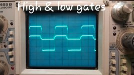
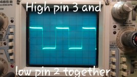
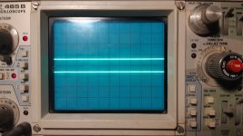
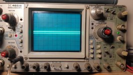
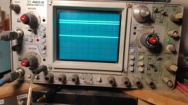
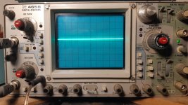
I went back to low power jig. It's making about +/- 30v. Have 2 probes running in every pic. 20v/div and 5us.
Everything seems to be running fine. Do these waves look ok? Before I try to go back to full power.
I went back to low power jig. It's making about +/- 30v. Have 2 probes running in every pic. 20v/div and 5us.
Everything seems to be running fine. Do these waves look ok? Before I try to go back to full power.
Attachments
Last edited:
Good evening Perry
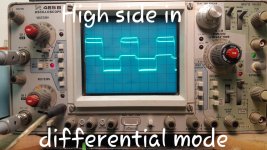
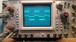
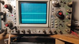
I get faint squiggly lines. I readjusted scope to 20v 10us. Both pins probing a drain. When I press the add button I get a 3rd trace that appears just above ch 2 trace. Not sure if it's suppose to do that. The first 2 are no remote. With and without the add button. The second 2 are remote on, with and without the add button.
I did get it to lock on for like a split second once when powering it up. But haven't been able to again to get a pic
Attachments
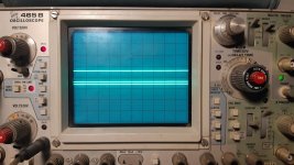
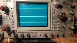
You're right. Something is not right... I have done the whole list. Both inputs on. Input set to add (which gives me that extra trace offset). Both channels to dc offset. Both vertical amps are set to 5v for this one. Ch2 set to invert. Traces are centered except for the added line that appears below soon as I hit add. Both leads are grounded together. Scope is grounded to power supply.
Channel 1 deflects the 2 traces up, channel 2 deflects the 2 traces down, both together one goes up, one goes down... and the added trace sits just below reference line
Channel 1 deflects the 2 traces up, channel 2 deflects the 2 traces down, both together one goes up, one goes down... and the added trace sits just below reference line
Attachments
- Status
- This old topic is closed. If you want to reopen this topic, contact a moderator using the "Report Post" button.
- Home
- General Interest
- Car Audio
- American Bass 1100.1