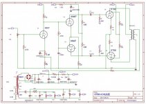
Assistance or advice needed please! I intend to build a PP KT88 amplifier. I have the transformers, chassis and valves from a previous KT88 PP amp. My question is would this circuit with a little modification be suitable for KT88 valves? The reason being that I bought a PC board from Ebay that uses this circuit. I have some experience with valve builds but my knowledge of theory is limited, although I'm learning a lot from this site. Please ask questions if I haven't given sufficent information or the answers are elementary. I'm not proud🙂.
Attachments
Yes, the short answer is it will work. And probably pretty nicely. Might need to tweak a few resistor values to really dial it in, but that can be done once it's up and running.

Yes it will work.Assistance or advice needed please! I intend to build a PP KT88 amplifier. I have the transformers, chassis and valves from a previous KT88 PP amp. My question is would this circuit with a little modification be suitable for KT88 valves? The reason being that I bought a PC board from Ebay that uses this circuit. I have some experience with valve builds but my knowledge of theory is limited, although I'm learning a lot from this site. Please ask questions if I haven't given sufficent information or the answers are elementary. I'm not proud🙂.
The board however might not. Look at the elevated DC on the LPT, it will have it's grid's
on the V1 plate voltage. In addition it will most likely be unbalanced unless the V2 is choosen very picky.
These days a CCS in the cathode will give better AC symmetry.
Thanks for your observation petertub, appreciated, but what do you suggest as a fix? I haven't started the build yet so any help is appreciated. I have been looking at a number of other circuits and they all seem to be of a similar nature.
The 12AU7 can handle 200V heater to cathode voltage.Yes it will work.
The board however might not. Look at the elevated DC on the LPT, it will have it's grid's
on the V1 plate voltage. In addition it will most likely be unbalanced unless the V2 is choosen very picky.
These days a CCS in the cathode will give better AC symmetry.
The Eico HF-89 uses a very similar arrangement, and works very well.
This will work without problems, you won't have to change much. KT 88's need a little more neg. grid voltage. The only thing you have to do is to readjust the neg. grid voltage. Start by putting the potmeters in the highest position (about - 90v I guess) and slowly turn it down until you measure 0,5v across each of the 10 ohm cathode resistors. Each tube now draws 50ma and that's all there is to it.
That's great, thanks for that. I was going to ask a few questions about the voltages and biasing further down the line, so thats very useful. Many thanks to all that have offered help so far. I will try to post pics of the build as it proceeds and hopefully any mistakes will be spotted in time!This will work without problems, you won't have to change much. KT 88's need a little more neg. grid voltage. The only thing you have to do is to readjust the neg. grid voltage. Start by putting the potmeters in the highest position (about - 90v I guess) and slowly turn it down until you measure 0,5v across each of the 10 ohm cathode resistors. Each tube now draws 50ma and that's all there is to it.
As #8 said drop R22 to 4K7 if you cannot get enough negative grid voltage on the KT88's to bring the bias down to the level you want. KT77 may be a closer match. R11, R10 are different value to get a balanced AC out of the LPT 12AU7. If you want a CCS then make R10, R11 33K replace R9 with a 15K in series with a LM334 and set to something like 6-8ma. You need some voltage across the LM334 no not so much as it gets hot. I would not bother with a CCS for now.
Last edited:
C2 and/or R4 might need some refinement to get a nice square response, provided you have an oscilloscope and a dummy load. It should work fine as is.
Thanks igormoh. I've started wiring the PCB, (slow progress as not much time) but I was looking at your diagram and I see there is a swith for UL or triode mode. The OT I have doesn't have a UL tap so I was going to wire pin 4 to 3 via a 100 ohm resister and connect up to P1 and run in triode mode only. I never really listen at very high volumes and I have reasonably high sensitivity Heybrook floor standing speakers from the mid 1990's that I really like.
Good day! My process is also slow. I soldered the amplifier a year ago, but then covid19 closed all stores and the project was frozen. This year I renewed it, photo. Look for experiments with another version of the scheme of Chinese engineers. 6n8p=6sn7 ~ ~ 12a ** 7.
Attachments
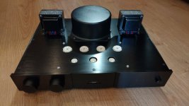
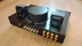
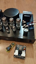
Hi igormoh,Good day! My process is also slow. I soldered the amplifier a year ago, but then covid19 closed all stores and the project was frozen. This year I renewed it, photo. Look for experiments with another version of the scheme of Chinese engineers. 6n8p=6sn7 ~ ~ 12a ** 7.
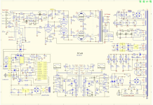
Some comments about the Oldchen schematic:
- C12 must be at least 450V. The 1.5K resistor is not going to drop 50V with the typical 6N8P LTP currents. Also, when the tube is cold, you will have there 450V if B+ is on. Maybe it makes more sense to use the +350 tap to power the LTP.
- Edit: C5/6/7/8 and C12 must be at least 500V, and that is still below the peak voltage you will get there at power up 360*1.414=509V. There is no B+ delay due to the use of a solid state rectifier.
- R8/R9 seem quite low, usually 100K is used for fixed bias.
- Both U1 and U2 are low mu triodes, ~20. Usually U1 would be a high mu one, like the 6N9P (6SL7), otherwise the open loop gain will be quite low, not enough for gNF to be effective.
Jose
Last edited:
- Home
- Amplifiers
- Tubes / Valves
- Amend EL34 circuit for KT88