Hi there
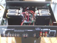
got a fragment from an AMC amplifier and would like to make it operational again with my existing components. The mains transformer and OPT´s are missing. Unfortunately there is no voltage information on the transformer or in the circuit in the available circuit documents. My existing transformer would have 340,390 and 410V 0.6A outputs for the anode voltage, which can I use for the amplifier? I added the original and modified circuit, the original amp has 80W per channel with 6550 tubes.
best regards
geänderte Schaltung
original Schaltung
I found an older circuit of the amp, but with UL Opt´s but unfortunately also without voltage information :-(
Schema
Attachments
Last edited:
FWIW, I salvage the chassis and the 6550s, if they are still good. Octal sockets on PCBs are trouble waiting to occur. Can you say cracking? Thermally vulnerable SS small signal circuitry that close to 6550 heat gives me reliability concerns. I suggest "idiot resistant" Mullard style circuitry along the lines of the H/K Cit. 5.
600 mA. RMS ends up being roughly 300 mA. DC and that's not enough for a quartet of 6550s. Perhaps Polish winder "Toroidy" can help you with suitable magnetics.
BTW, I find your "moniker" of "snapper" interesting. This is what I think of, when "snapper" is mentioned. Give that "critter" respect or potentially loose body parts.
Attachments
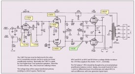
Well… here's my first-round calculation. Note, in order for the 12BY7 to have a 'meaningful' operating point, its VSCREEN must be well below B+. As shown.
Just saying,
⋅-=≡ GoatGuy ✓ ≡=-⋅
Just saying,
⋅-=≡ GoatGuy ✓ ≡=-⋅
Attachments
Last edited:
The 12BY7 is getting scarce and available stock is (IMO) best reserved for already constructed units.
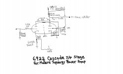
I'm providing a 6922 cascode to substitute for the 12BY7. Stage gain is quite comparable.
What's superior about the Cit. 5 is the use of high gm types in the small signal circuitry. That idea can be carried further by using an ECC99 as the LTP.
CCS loading the LTP tail is another area of potential improvement.
Attachments
here is a 6922 cascode to substitute for the 12BY7. Stage gain is quite comparable.
What's superior about the Cit. 5 is the use of high gm types in the small signal circuitry. That idea can be carried further by using an ECC99 as the LTP.
CCS loading the LTP tail is another area of potential improvement.
I just don't like CCS loading. Over life of valves, is waaaayyyy too sensitive to operating point parameters, causing quite the long-term drift in VA. CCS tho' is plenty-good for VK auto-biasing. Either naked (i.e. not capacitor bypassed) or … bypassed to achieve low A/C impedance.
Its a personal foible, I admit … but I don't much like cascode presented as two-triodes-in-one-envelope as you did. As I said, my foible. Carry on!
⋅-=≡ GoatGuy ✓ ≡=-⋅
sorry, my question was about the required anode voltage and not about a new design.
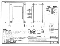
I also have opt's (made in USA ;-)) that I would also like to use!
I also have opt's (made in USA ;-)) that I would also like to use!
Attachments
Last edited:
sorry, my question was about the required anode voltage...I also have opt's ....
Attachments

- Home
- Amplifiers
- Tubes / Valves
- AMC CVT tube amplifier anode voltage?