Happy and hopefully better new year 2021
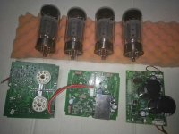
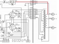
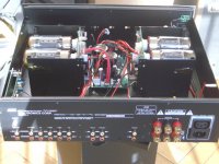
I have the power amplifiers and PSU boards from an AMC tube amplifier and maybe play with the idea of using them in a DIY project. What makes me suspicious is that the cathodes of the power tubes are connected to ground via an extra winding on the transformer !? Since I don't have a suitable transformer yet, it will be difficult to find one with an extra winding. Can someone explain to me what the whole thing should be for? What happens if the cathodes are connected directly to ground as usual?
greeting
Attachments
Last edited:
With an exact 4-(8)-16 speaker winding cathode NFB will work, and usually adequate. Determining phasing of all three windings will make you crazy.
Otherwise replace tertiary with jumpers.
Otherwise replace tertiary with jumpers.
thank you, but this is not available anyway as the OPT can only be purchased expensively directly via amc (if at all) and a production is eliminated because of the unknown winding data !
I was actually concerned with the question of why the whole thing should be good / function ?
So just pull the cathodes to ground via 2R 3W !?
I was actually concerned with the question of why the whole thing should be good / function ?
So just pull the cathodes to ground via 2R 3W !?
Attachments
@snapper
Since you have to use O/P "iron" other than AMC's, consider "routine" ultra-linear "finals". Very little trace cutting would be needed. This item sourced "next door" in Poland seems to be favorably priced.
Anything other than what AMC used requires reworking of the phase compensation.
Mullard style small signal circuitry will be quite safe.
Connecting the cathode to a winding on the output transformer (cathode feedback, or CFB) is similar to connecting the screen grids to a winding (tap).
Look at it from the point of view of the cathode (% as examples):
Pentode mode 100% Vac anode, 0% g2.
UL mode 100% Vac anode, 42% g2.
CFB mode 100% Vac anode, 20% g2.
We are used to look from the perspective of ground, in which case CFB looks like anode 80%, g2 0%, cathode 20% (opposite phase to anode).
CFB is more effective as it is partial cathode follower as well as intermediate between pentode and triode like UL.
Transformers are more expensive since you need a dedicated winding instead of just taps on the primary.
And you need considerably more swing from the driver, as that needs not only to drive the output tubes, but also to overcome the ac on the cathode.
Just a little CFB by using a symmetrical speaker secondary (0-2-8 or 0-4-16 with the middle tap grounded) is already beneficial and easy on the driver.
great, thanks for the toroidy.pl info.
which voltages / currents does the mains transformer have to supply?
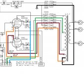
the amp has 2x 80W in the original, from the circuit diagram I can see B+ 355V CT 710V, bias 100V but unfortunately no current information, although for bias I could use a small extra transformer if necessary !
Heater at 6.3V 6.6A, at 12.6V 3.3A
I think they also make custom-made items:
"Did not find the transformer you were looking for? Please write to us or give us a call"
which voltages / currents does the mains transformer have to supply?
the amp has 2x 80W in the original, from the circuit diagram I can see B+ 355V CT 710V, bias 100V but unfortunately no current information, although for bias I could use a small extra transformer if necessary !
Heater at 6.3V 6.6A, at 12.6V 3.3A
I think they also make custom-made items:
"Did not find the transformer you were looking for? Please write to us or give us a call"
Attachments

Hi,
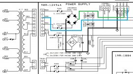
calculated from the DC voltages, the original mains transformer supposedly has a 250-0-250 Vac plate supply winding.
Best regards!
calculated from the DC voltages, the original mains transformer supposedly has a 250-0-250 Vac plate supply winding.
Best regards!
Just to explain. Its a form of negative feedback. When the plate of one output falls the cathode increases in voltage causing the plate to raise again. It has the effect of reducing the output impedance and improving damping factor. Similar to ultra-linear but not limited with max g2 voltage.
Yes, however it will turn your amp into a pentode output. The is make the damping factor much higher, and will increase distortion and you may well need to adjust the NFB. It was done for a reason if you see what I mean. Somebody suggested a 0-4-16r transformer (this has actually equal turns on the 0-4 and 4-16 taps) and ground the centre tap. However that means you will probably need a 4 or 16 speaker. Also I don't know if the turns ratio is correct for the NFB to work as intended.
Yes, however it will turn your amp into a pentode output. The is make the damping factor much higher, and will increase distortion and you may well need to adjust the NFB. It was done for a reason if you see what I mean. Somebody suggested a 0-4-16r transformer (this has actually equal turns on the 0-4 and 4-16 taps) and ground the centre tap. However that means you will probably need a 4 or 16 speaker. Also I don't know if the turns ratio is correct for the NFB to work as intended.
The Polish O/P "iron" I previously suggested comes with "conventional" ultra-linear (UL) taps. 100 Ω "safety" resistors in the g2 lines should provide adequate protection for current production KT88s and 6550s. Any O/P "iron" other than AMC's original will involve some o'scope time getting phase compensation squared away. AFAIK, the OP has a PSU PCB and 2 O/P stage PCBs, but does not have small signal stuff. Given the fact that Mullard style small signal circuitry is "idiot resistant", I repeat the suggestion that Mullard style topology be employed.
Agree UL is a good option. Just need to watch vg2 for the 6550, I've been OK for 430V with the EH ones. Or KT88. The HT volts is somewhere on this post.
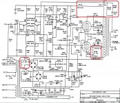
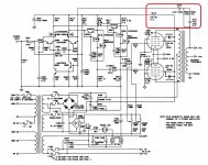
According to both schematics in the 1st posting, HT voltage (named CT) is 710 Vdc, screen voltage (named B+) is 355 Vdc.
As the thread starter apparently hasn't the original iron, he's totally free in designing his own amp. Maybe the venerable M&A TVA 1 might lend a clue regarding PT and OT's?
Best regards!
As the thread starter apparently hasn't the original iron, he's totally free in designing his own amp. Maybe the venerable M&A TVA 1 might lend a clue regarding PT and OT's?
Best regards!
Then I think you will need to combine the UL, plate and 0V with three resistors and then buffer (emitter follower or MOSFET or say ECC88 with elevated heater) to get the correct UL and Vg2 within range. Getting complicated. Or floating UL taps. Maybe that's why its done on the cathodes.
snapper,
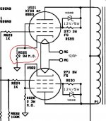
Your post #3 shows Triode wired mode.
Using 270 Ohm screen resistors, in parallel with a Zener diode will cause a large transient change when the screen current turns on the Zener. I call this a cause of signal dis-continuity, it could be a transient caused distortion.
The problem is the same for UL mode, and for Beam Power mode, if you use parallel 270 Ohm and Zener to the screens.
Have fun designing, building, and listening.
baudouin0,
Using 'Pentode' mode (more accurately for a 6550 'Beam Power' mode), will Reduce the damping factor, not make the damping factor higher.
I think you did like I sometimes do, think one direction, and use the opposite word. The output impedance becomes higher.
If you ground the 4 Ohm tap, and use the Common tap and 16 Ohm tap for the cathode feedback, then you simply connect the 8 Ohm speaker between the common tap, and the 8 Ohm tap (the speaker is 'floating' but is connected DC wise to ground, so it is safe).
The problem is you can not test the amp with an 8 Ohm load resistor, because the scope ground, and the common tap will fight each other.
So use a 4 Ohm test load, connect the 4 Ohm resistor from either Common and 4 Ohm taps, or from 4 Ohm tap to 16 Ohm tap.
Connect the scope from ground (the 4 Ohm tap) to the Common tap (hot), or ground (4 Ohm tap) to the 16 Ohm tap (hot).
Should work OK. I have done it before.
Last edited:
I found an older circuit from the AMC, according to the manual also 2x 80W, so the polish opt with UL would fit well (unfortunately no % information from AMC) HV winding mains transformer without center tap, unfortunately I also lack the current and voltage information, adjustment FB required and a few other small changes, marked in red in the scheme!
I really want to use this pcb because I also have a suitable case!
I really want to use this pcb because I also have a suitable case!
Attachments
Cathode Feedback PP, seems to be the new concept !?
Cathode Feedback PP - Shop Toroidy.pl
other distributor of polish transformers
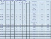
Mains transformers for vacuum-tube amplifiers, TSL series, TSL15/001, TSL40/001, TSL40/002 |EN|
Cathode Feedback PP - Shop Toroidy.pl
other distributor of polish transformers
Mains transformers for vacuum-tube amplifiers, TSL series, TSL15/001, TSL40/001, TSL40/002 |EN|
Attachments

Last edited:

- Home
- Amplifiers
- Tubes / Valves
- AMC CVT 6550 power amplifier Understanding question, what is the trick?