I have an Amber series 70 with what seems to be defective LM391N-100 chips in both channels. I have 'Fluke meter' checked every diode, the drivers, and outputs and all test OK in circuit.
I am considering taking a chance on a 'off shore' source for the chip but would appreciate ideas on the best source. Also any other tests that could be performed before inserting the new chips?
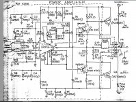
The Amp powers up and fuses hold with driver boards installed and chips removed. One of the chips will smoke the two 68 ohm series resistors to pins 15 and 16. The other chip does not burn these resistors but send the speaker output to +38 VDC.
I am considering taking a chance on a 'off shore' source for the chip but would appreciate ideas on the best source. Also any other tests that could be performed before inserting the new chips?
The Amp powers up and fuses hold with driver boards installed and chips removed. One of the chips will smoke the two 68 ohm series resistors to pins 15 and 16. The other chip does not burn these resistors but send the speaker output to +38 VDC.
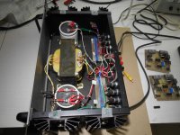
Attachments
Been watching the 2021 NBC un-RoseBowl Parade. Still fun without the streets or crowds. External amped sound over an 8" woofer 3 way speaker replaces **** flat TV sound.
LM391 won't be real from anywhere. The +-38 volts leaves out a lot of IC solutions like LM3875 or LM3886. The TDA7294 would suit, if it is still in production.
However, you have working drivers and output transistors, it appears. I would remove the LM391 and graft in 2 transistors from an Apex AX6 on a 1.5" square bare board. Retro Amp 50W Single Supply - Page 22 - diyAudio
That is a MPSA56 or 2n5400 or 2n5401, followed by a 30 mhz VAS like MJE15028. I used GE D44R4 for VAS, but you can't buy those anymore. Put a heatsink on the VAS. I did, and ran my up to 14 hours a day. Don't waste time with a TIP31c or 41c. I used that first and sound lacked highs versus the 1970 RCA VAS & drivers surviving on the original ST120 channel. You might need to increase some resistor values because the supply is 76 volts instead of 70 for the original AX6 design.
The two spreader diodes between the bases of the drivers mount on a solder terminal strip over the output transistor heat sink. I used a mini coil from a dead switcher supply in the line coming back from the diodes to the feedback of the emitter of the pnp transistor, to prevent oscillation.
I use nema CE board for my AX6, McMaster-Carr that I drill myself. You can also use vero board. Soldering the wires on, teflon or kynar insulation makes for less bare spots when the iron hits the insulation. Board is mounted to the chassis with standoffs & #6 x 1" screws. Use elastic stop nuts so they don't come unscrewed.
Have fun.
Last edited: