Hello! I am building the Elenco AM-550CK kit. All has gone well...up to...measuring AC Bandwidth (pg14 of manual).
When I increase frequency, the sine wave does not lower at all from it's original setting. Also, when the frequency is lowered...still cant get any visual change of voltage.
What I do see is the frequency change along the horizontal axis.
Any help will be greatly appreciated!
Thank You!
Tony
When I increase frequency, the sine wave does not lower at all from it's original setting. Also, when the frequency is lowered...still cant get any visual change of voltage.
What I do see is the frequency change along the horizontal axis.
Any help will be greatly appreciated!
Thank You!
Tony
Attachments
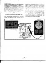
Starting at 1KHz, increased to 2KHz and lowered to 100 MHz.
It seems there is no effect on voltage?
It seems there is no effect on voltage?
As a beginner, I am not sure of much! I do not know what hum or mains frequency refers to. I cant seem to get the sine wave to reduce in (amplitude?).
The test seems to be just to confirm the audio output stage bandwidth... just for education I guess.
Does the radio actually work ?
If you connect just the scope to the generator (no radio involved) can you alter the frequency of the signal and see it alter on the scope ? Make sure you understand the frequency scale.
A good generator will maintain a constant output as frequency is varied. Most generators won't cover a wide range in one go, you have to alter the range for example 10 to 100hz and 1Khz to 10khz etc.
It might help to know what generator you are using 🙂
The 10uf cap to the generator must have the positive end to the transistor.
This is the first completed section only of the build; the Audio Amplifier.No other part of the radio had been built.
Sound(tones) do come from the speaker, and vary with frequency change.
I purchased a few generators and counters ( ebay ), but between them all, I think the frequency applied is "fairly" accurate.
Generator alone with scope does produce a clean signal, which will change as the generator is adjusted, including the magnification(range) dial.
The 10uf cap has been checked for correct polarity/installation.
Your mention of this being a bandwidth measure seems like this is exactly what is happening here...only!
Scope lead is connected to Ch1, X axis. AC measuring.
Is it possible I need to connect the circuit to the Y axis also?
Sound(tones) do come from the speaker, and vary with frequency change.
I purchased a few generators and counters ( ebay
), but between them all, I think the frequency applied is "fairly" accurate.Generator alone with scope does produce a clean signal, which will change as the generator is adjusted, including the magnification(range) dial.
The 10uf cap has been checked for correct polarity/installation.
Your mention of this being a bandwidth measure seems like this is exactly what is happening here...only!
Scope lead is connected to Ch1, X axis. AC measuring.
Is it possible I need to connect the circuit to the Y axis also?
By '100MHz' I assume you mean 100Hz? 100Hz to 2kHz is likely to be well within the circuit bandwidth - it certainly ought to be for an audio amp! Try the region 10-100Hz, and 10-100kHz. Then you might see something. When looking for an effect, it can be helpful to have some idea what you are looking for.
That sounds to be working OK then if the speaker outputs the tones.
If you measure the signal across the speaker (the peak to peak voltage) and do the same for the input signal you can calculate the gain by dividing the output figure by the input figure. That will be related to the feedback resistor values R15 and R16.
If you measure the signal across the speaker (the peak to peak voltage) and do the same for the input signal you can calculate the gain by dividing the output figure by the input figure. That will be related to the feedback resistor values R15 and R16.
When looking for an effect, it can be helpful to have some idea what you are looking for.
Great truth!!!
- Status
- Not open for further replies.
- Home
- Design & Build
- Construction Tips
- AM Radio Kit Question