Hey everyone. I was not sure where this question should go. It is loosely related to diy audio. I have built an AM radio receiver from scratch. It is a simple design that includes a RF amp at the front end followed by a detector which feeds into a two stage audio amp. When I feed an AM signal from my generator into the receiver it works perfectly. The problem is when I connect the antenna in place of the generator. I do not hear anything. However, when I touch the antenna with my hand, I can hear the radio station pretty well. Does anyone have an idea of why this is happening?
The antenna is a loop type. Basically it is a piece of wire wrapped around a box. A trim cap is used to tune it to a resonance frequency of the desired radio station. I can give more detail if necessary. Thanks.
The antenna is a loop type. Basically it is a piece of wire wrapped around a box. A trim cap is used to tune it to a resonance frequency of the desired radio station. I can give more detail if necessary. Thanks.
Because you're well grounded i.e. you have no potential.
kidding aside.
or are you de-Qing the tank possibly (wider BW). Access to a network analyzer?
1) best >long wire ant
2) better> ferrite bar
3) air loop
If you use a long wire antenna and connect the low side of the LC tank to a good earth ground this should cure that effect for good.
kidding aside.
or are you de-Qing the tank possibly (wider BW). Access to a network analyzer?
1) best >long wire ant
2) better> ferrite bar
3) air loop
If you use a long wire antenna and connect the low side of the LC tank to a good earth ground this should cure that effect for good.
Loops cancel most noise that could be induced by your hand, because they are inherently balanced devices.
I'd stick to the loop variety of antennas for AM. The noise on those bands is horrendous and loops for the most part, are immune.
Cheers!
I'd stick to the loop variety of antennas for AM. The noise on those bands is horrendous and loops for the most part, are immune.
Cheers!
Can you post an image of the physical build? thanks
OT Not really a noise issue at the moment. Long wire is best for Dx.
OT Not really a noise issue at the moment. Long wire is best for Dx.
THIS is a DX loop for those lower frequencies 
http://geek.scorpiorising.ca/GeeK_ZonE/index.php?topic=3929.0
http://geek.scorpiorising.ca/GeeK_ZonE/index.php?topic=3929.0
The design I am using came from http://www.mindspring.com/~loop_antenna/
I am trying to tune in the AM radio broadcast band. Specifically I am trying to get 1230kHz. I will try to get some pictures so you can see what I am dealing with.
Thanks for all the responses so far.
I am trying to tune in the AM radio broadcast band. Specifically I am trying to get 1230kHz. I will try to get some pictures so you can see what I am dealing with.
Thanks for all the responses so far.
Mark245
Please post a picture of the radio and more importantly a schematic. If in fact you have only the loop antena and a tuning cap you don't have enough selectivity in that design. When you say that you are going from an RF amplifier right into a detector that is leaving out the mixer, and some other things. Its long been accepted pratice to mix down to an intermeadate frequency and incorporate still more filtering. In short you have whats called a TRF "tuned RF" radio and they are finiky at best. This might mean more parts, but it will me much better. Look up the "Superhetrodyne Principal" Oh,- and this topic is a little unusal for this forum, I hope I'm not out of line.
Please post a picture of the radio and more importantly a schematic. If in fact you have only the loop antena and a tuning cap you don't have enough selectivity in that design. When you say that you are going from an RF amplifier right into a detector that is leaving out the mixer, and some other things. Its long been accepted pratice to mix down to an intermeadate frequency and incorporate still more filtering. In short you have whats called a TRF "tuned RF" radio and they are finiky at best. This might mean more parts, but it will me much better. Look up the "Superhetrodyne Principal" Oh,- and this topic is a little unusal for this forum, I hope I'm not out of line.
Hi
Must be using some super tuner. Wonder... who do they want to hear so badly in the US?
http://www.universal-radio.com/catalog/mwant/0445.html
Must be using some super tuner. Wonder... who do they want to hear so badly in the US?
http://www.universal-radio.com/catalog/mwant/0445.html
Its 12 inches long @ 2 inches diameter
If'n it were my project I'd use a really big ferrite rod similar to what these folks use/sell. Probably use several different litz windings for peaking and impedance matching. Forget transitors and big air coils. Preamp would be a LN current feedback op-amp with a balanced ferrite LPF.
AGC is must for any kind of AM tuner! also a good IF filter for selectivity couldn't hurt. But then you need a good local oscillator. All been done before us.
oops...almost forgot the link http://www.stormwise.com/11AM-530K-1710K-SP-BNC-datasheet.htm
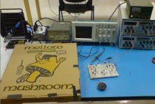
Ok here is a picture and schematic of what I am dealing with. Actually this is a class project for the lab I teach. We basically want to build a simple AM receiver for 1230kHz and when it works, turn it into a heterodyne receiver. We just wanted to make it as simple as possible at first.
All of the circuitry is on the breadboard. The antenna consists of magnet wire wrapped around a pizza box as shown in the photo. It has 7 loops. According to the Joe Carr formula, this will give an inductance of 61uH. So to resonate this antenna at 1230kHz, we need a 270pF cap. When I use these values, I get nothing from the speaker but like I say, when I touch the conductor from the antenna to the RF amp input, the radio station comes through pretty well. If I can get the radio to work without having to touch the antenna with my hand then it will be a success. Thanks for the advice so far and any other thoughts will be appreciated.
Thanks. Mark.
Attachments

Hi
I think you should try to "balance the antenna" by using a buffer between the LC tank and the breadboard with a common mode choke.
Use smaller twin lead wire wrap about 15-20 turns around a ferrite toroid (26 AWG speaker zip cord is OK) and get a little more distance too.
If that fails checK the resonace and determine Q of the tank.
Sweep the generator with a small series resistor ( 100 ohm use for current). Find the peak Vpk and the 1/2 power points. 0.707Vpk.
edit>I'm sure the choke is going to fix it for you tho.
good luck

AM Long wire DX
Last year a guy in Quoddy Head, Maine (Eastern most point of land in the continental USA.) got recorded contacts in Saudi Arabia in the day.
Here is link to his Dx log http://www.kongsfjord.no/dl/DX-peditions/Quoddy Head DXpedition rev 8.pdf
scroll to last page for pictures and interesting story.
excerp
"It is a good thing I started early. The BOG's were operational by 3 pm EDT (1900 UTC) and I was doing a little casual listening to domestics in 6 kHz BW AM mode when I came across a big het on 1520. So I changed to 3 kHz BW USB and tuned 1521. There was Saudi Arabia virtually in the clear. In 20+ years of listening in Louisiana and Texas I gave gotten clear 1521 Saudi Arabia audio exactly once. To do it here at Quoddy Head, Maine at 3:15 pm EDT some 2.5 hours before sunset was amazing to me"
Infinia, You mean put the RFC in parallel with the LC tank of the antenna right? I tried this with a 10000uH inductor. I still have to touch the antenna with my fingers at the input to the RF amp to make it work. However, it does make the signal sound a little better.
I also tried putting the RFC in series with the antenna. I assume this is not what you meant because it completely blocks the RF signal. Should I try using the wire wrapped around a torroid like you mentioned? Thanks for the help.
I also tried putting the RFC in series with the antenna. I assume this is not what you meant because it completely blocks the RF signal. Should I try using the wire wrapped around a torroid like you mentioned? Thanks for the help.
Hi
Yes use a common mode choke betwen the LC and the preamp
see link Fig 4 http://www.audiosystemsgroup.com/RFI-Ham.pdf
Like in Fig 4 but instead of coax you will use twin lead 26AWG speaker zip wire.
Yes use a common mode choke betwen the LC and the preamp
see link Fig 4 http://www.audiosystemsgroup.com/RFI-Ham.pdf
Like in Fig 4 but instead of coax you will use twin lead 26AWG speaker zip wire.
Attachments
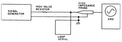
Measurement of loop constants for a high Q LC tank circuit
These factors can be measured using a signal generator fed via a fairly high resistance (say 10 k) to the loop as shown in Figure 1. The voltage across the loop is monitored on a CRO (or perhaps a VTVM) via a high impedance probe. The signal generator frequency is adjusted for a peak in voltage at which the natural frequency is indicated.
Having measured the self-resonant frequency
As a further operation, Q factor can be measured using the same equipment, except that the resistance in series with the signal generator must be increased to around 500 kohm to prevent the Q being lowered by the signal source. With extra signal loss across the resistor, a high signal level and a sensitive CRO are needed. The procedure is simply to measure the frequencies either side of resonance which give 0.707 of the voltage at resonance. The Q factor is equal to the resonant frequency, divided by the difference between the two frequencies recorded.
Q=fc/BW where fc= freq maxima and, BW= f2 - f1
f1 =0,707 Vpk freq of low side -3dB point
f2 =0,707 Vpk freq of high side -3dB point
Figure 1 - Measurement of Loop Aerial constants
Attachments
- Status
- Not open for further replies.
- Home
- Design & Build
- Parts
- AM Radio Antenna