Konnichiwa,
Well, I know what I would recommend.
If you use cascaded local single transistor AC only shunt using low noise BJT's and sensible value series resistors fed from a reasonably low noise Regulator (317 optimised will do) you can get mightily close to the final BJT's own noise with excellent AC behaviour as well...
Sayonara
peranders said:What do you recommend then?
Well, I know what I would recommend.
If you use cascaded local single transistor AC only shunt using low noise BJT's and sensible value series resistors fed from a reasonably low noise Regulator (317 optimised will do) you can get mightily close to the final BJT's own noise with excellent AC behaviour as well...
Sayonara
Kuei Yang Wang said:Konnichiwa,
Well, I know what I would recommend.
If you use cascaded local single transistor AC only shunt using low noise BJT's and sensible value series resistors fed from a reasonably low noise Regulator (317 optimised will do) you can get mightily close to the final BJT's own noise with excellent AC behaviour as well...
Sayonara
Hi Sayonara,
I fully agree here, but why AC only ? The 1/f noise of a 317 is not that low so you may want to get rid of that too......
best
Konnichiwa,
Depends really on the value of the capacitor linking Collector and Base and the Bias Resistors. Methinks my application has an F3 of 0.16Hz or so, which means there I loose only 3db filtering. Anyway, I think the question is one of definition.
Sayonara
Guido Tent said:I fully agree here, but why AC only ? The 1/f noise of a 317 is not that low so you may want to get rid of that too......
Depends really on the value of the capacitor linking Collector and Base and the Bias Resistors. Methinks my application has an F3 of 0.16Hz or so, which means there I loose only 3db filtering. Anyway, I think the question is one of definition.
Sayonara
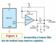
Take a look at the LT1019 series of references, they are very quiet and also extremely stable. Note that you can also use active LPF (sallen key ) after the reference if you need/want something even quieter - just be certain to use small resistors <1K set corner below 100Hz and make sure that the op-amp you use is <10nVrtHz and also low noise below 10Hz, like say op2177arm.. I use a 3rd order filter implementation with the final filter pole in the ouput and use a lag compensation network to set the op-amp dominant pole somewhat below the output pole. Very quiet and commonly used in ATE applications where we need very quiet dc for testing A/D and D/A chips.
I can post further details if anyone is interested...
Kevin
I can post further details if anyone is interested...
Kevin
. I use a 3rd order filter implementation with the final filter pole in the ouput and use a lag compensation network to set the op-amp dominant pole somewhat below the output pole.
Please post schematic. I am interested in learning how you implemented the filter.
What about blue LED followed by op amp with necessary gain for desired output voltage ?
I saw PSU regulators with green LED and transistor in Akai CDP.
I saw PSU regulators with green LED and transistor in Akai CDP.
kevinkr said:Take a look at the LT1019 series of references, they are very quiet and also extremely stable. Note that you can also use active LPF (sallen key ) after the reference if you need/want something even quieter - just be certain to use small resistors <1K set corner below 100Hz and make sure that the op-amp you use is <10nVrtHz and also low noise below 10Hz, like say op2177arm.. I use a 3rd order filter implementation with the final filter pole in the ouput and use a lag compensation network to set the op-amp dominant pole somewhat below the output pole. Very quiet and commonly used in ATE applications where we need very quiet dc for testing A/D and D/A chips.
I can post further details if anyone is interested...
Kevin
Hi Kevin
Interesting. What is the final noise you achieve at the output ?
best
Ron Mancini of TI discussed this in the Nov 25 2004 issue of EDN (methinks he would prefer you use Burr Brown OpAmps and References 🙂 )kevinkr said:Take a look at the LT1019 series of references, they are very quiet and also extremely stable. Note that you can also use active LPF (sallen key ) after the reference if you need/want something even quieter - just be certain to use small resistors <1K set corner below 100Hz and make sure that the op-amp you use is <10nVrtHz and also low noise below 10Hz, like say op2177arm.. I use a 3rd order filter implementation with the final filter pole in the ouput and use a lag compensation network to set the op-amp dominant pole somewhat below the output pole. Very quiet and commonly used in ATE applications where we need very quiet dc for testing A/D and D/A chips.
I can post further details if anyone is interested...
Kevin
Attachments
Here's another article on the TL431 from the folks at TI -- it follows another discussion in Switching Power Magazine last year which discussed methods of compensation:
http://www.edn.com/contents/images/091505di.pdf (go to page 5 of the PDF)
http://www.edn.com/contents/images/091505di.pdf (go to page 5 of the PDF)

kevinkr said:Hi,
This circuit is quite similar to what I have been using and works well.
It is a little more complicated than that shown above but provides noise attenuation from 10Hz on up.
Kevin
Hi
Allright, thanks
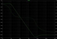
Looks good, but still for LF the noise is unattenuated. Won't hurt for most applications, but for oscillators it is vital.......
best
Konnichiwa,
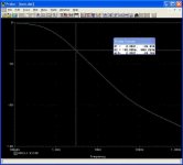
Well, my little 2 transistor circuit using otherwise generic parts looks like the attached in p-spice. This follows a 317....
Sayonara
Guido Tent said:Looks good, but still for LF the noise is unattenuated. Won't hurt for most applications, but for oscillators it is vital.......
Well, my little 2 transistor circuit using otherwise generic parts looks like the attached in p-spice. This follows a 317....
Sayonara
Attachments
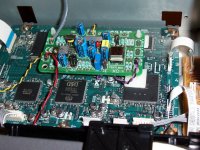
What about a CRC before the reg, on the unregulated PSU?
Guido sells an optional (L+C) unregulated PSU for his clocks.
Here it is, on the top left corner.
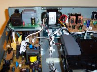
This is a Sony DVP-NS900V I modded for a friend.
I had to change the BG cap, otherwise the PSU didn't fit inside the player.
Guido sells an optional (L+C) unregulated PSU for his clocks.
Here it is, on the top left corner.
This is a Sony DVP-NS900V I modded for a friend.
I had to change the BG cap, otherwise the PSU didn't fit inside the player.
Attachments
Konnichiwa,
I would think it obvious.
My complete solution uses schottky diodes, CRC with small first capacitor and optimised LM317 (optimised output and adj bypassing) and dual simple single transistor cleanup shunt.
Over the 40KHz bandwidth that matters for multibit DAC's that gives around 25uV RMS after the LM317. The cleanup shunts knock it down pretty much to transistor noise above a few Hz, so use a low noise transistor in the final position and < 0.2uV noise is on the cards above a few Hz, while very low rate jitter/phasenoise is obviously measurable, it's audibility is another story....
All that is done using very generic parts and with good AC behaviour due to minimised and insulated feedback loops and not using "heroic" overbuild designs, the people who I pulled this from call this approach "Finesse".
Sayonara
carlosfm said:What about a CRC before the reg, on the unregulated PSU?
Guido sells an optional (L+C) unregulated PSU for his clocks.
I would think it obvious.
My complete solution uses schottky diodes, CRC with small first capacitor and optimised LM317 (optimised output and adj bypassing) and dual simple single transistor cleanup shunt.
Over the 40KHz bandwidth that matters for multibit DAC's that gives around 25uV RMS after the LM317. The cleanup shunts knock it down pretty much to transistor noise above a few Hz, so use a low noise transistor in the final position and < 0.2uV noise is on the cards above a few Hz, while very low rate jitter/phasenoise is obviously measurable, it's audibility is another story....
All that is done using very generic parts and with good AC behaviour due to minimised and insulated feedback loops and not using "heroic" overbuild designs, the people who I pulled this from call this approach "Finesse".
Sayonara
Kuei Yang Wang said:I would think it obvious.
My complete solution uses schottky diodes, CRC with small first capacitor and optimised LM317 (optimised output and adj bypassing) and dual simple single transistor cleanup shunt.
We are doing similar things, then. 😎
Kevin -- could you post a pic with a clearer view of the axes (or just email me jack@tech-diy.com)
Some of these TL431 "Noise Fixes" cause other problems -- remember, it's an "opamp mit reference avec pass transistor" with reactive elements and .AC analysis is required.
Some of these TL431 "Noise Fixes" cause other problems -- remember, it's an "opamp mit reference avec pass transistor" with reactive elements and .AC analysis is required.
Konnichiwa,
Could you please show a schematic for the psu you are talking about??
Thanks all for your input.
Keep em going
Kim
😀
Konnichiwa,
The specific implementation and design is for a commercial product and will not be placed in the public domain.
You can find information on the principles involved on the website of wenzel associates under the topic "Finesse Voltage Regulator Noise!".
To get the kind of performace I showed you MUST optimise the circuit first in P-Spice and later in the real world with real parts.
My aim was merely to show that to get low noise needs nothing too spectacular or complex, especially when powering oscillators.
Using a passively and actively filtered buffered reference is where a good reference is needed is again obvious, however you really need to dig out low noise Op-Amp's to equal simple transistor shunts.
Sayonara
kimschips said:Could you please show a schematic for the psu you are talking about??
The specific implementation and design is for a commercial product and will not be placed in the public domain.
You can find information on the principles involved on the website of wenzel associates under the topic "Finesse Voltage Regulator Noise!".
To get the kind of performace I showed you MUST optimise the circuit first in P-Spice and later in the real world with real parts.
My aim was merely to show that to get low noise needs nothing too spectacular or complex, especially when powering oscillators.
Using a passively and actively filtered buffered reference is where a good reference is needed is again obvious, however you really need to dig out low noise Op-Amp's to equal simple transistor shunts.
Sayonara
- Status
- Not open for further replies.
- Home
- Source & Line
- Digital Source
- Alw,Jan didden, Guido please help with TL431