Hi Community,
I have an Alpine MRP-M650 that I am trying to repair that has some really strange behavior. With power applied and remote power applied, there is no rail to rail oscillation.
However, when a large signal is applied to the input, the amp comes to life, at high output, obviously, but when turned down, or if the input is completely removed, the rail to rail oscillation remains and the amp operates normally.
There are no output FET damage or any other obviously failed components. All the MOSFET driving signals look good, etc. The output section does run in the low 300 KHz, which is higher than some amps, but I recall from another Alpine that it also ran in the 300s.
I would love to look at the schematic and see where the output clock is generated.
Thanks for input!
Albert
You are correct, some amplifiers will not start the oscillation without input.
With this particular amplifier it will not start until the level of the input is close to a level that resulting in clipping.
Also, because there is no rail to rail oscillation in the output section, the output voltage is not really controlled, until the unit starts, as described above.
With this particular amplifier it will not start until the level of the input is close to a level that resulting in clipping.
Also, because there is no rail to rail oscillation in the output section, the output voltage is not really controlled, until the unit starts, as described above.
Hi All,
I have spent hours looking and measuring this amp and am still no closer to solving this. As a reference I am using the MRD-M1005 Service Manual and schematic, which is a very similar.
I can see a triangle wave on the output of both the NJM2136 (pin6), once I have the amp started up with a high volume input, but it will not start when remote is applied initially.
Can anyone explain to me how the clock is generated and what could cause this behavior?
Steps that I have taken:
- Power Supply Working as normal, generating both +-32V Rails, +-15V Analog and +- 5V used by the NJM2136.
- Measured all the supply voltages to all the operational amplifiers, all normal
- I even re soldered all the through hole components around the NJM2136, since some of those film capacitors I thought may have been part of the oscillating circuit.
Is the triangle waveform a good solid signal with good amplitude ir more like noise?
What points have signals that change from no oscillation to normal operation?
What points have signals that change from no oscillation to normal operation?
Last edited:
NJM2136 Measurements
The triangle wave is about 0.5V peak to peak (not as large as I would have tough) and is offset on -2.0V. It looks a little noisy (if I am grounded on the battery ground), but if I ground to the A_GND it is fine.
Before Oscillation
For the NJM2136:
P1: 5.0V
P2: -0.2V
P3: 0.00V
P4: -5.0V
P5: Did not measure
P6: 4.2V
P7: 5.0V
P8: 5.0V
With no oscillation, there is no signal leading to the TC4069s and the IR2010S drivers do nothing.
Once Oscillating
P6: -2.0V with 0.5V ptp triangle wave.
The signal entering the TC4069s are initially really small on pin 1 and then as it propagates through the gates the signal gets larger and squares off.
I am used to the audio coming in on the one input of the OPAMP and the triangle wave on the other pin and it being used as a comparitor to create the PWM. Here the non-inverting input seems to be connected to the A_GND, so is the integration happening in Q301 - Q304?
Apologies if I am completely lost.
I don't think this is a clocked amp. Very few are.
Look at the M1000 amp. It's a simplified version and it definitely looks like it's self oscillating.
http://www.bcae1.com/temp/alpine - SM - MRP-M1000.PDF
Looking at the 1005 diagram, do you have 5v on one terminal of R315 when it won't oscillate?
Look at the M1000 amp. It's a simplified version and it definitely looks like it's self oscillating.
http://www.bcae1.com/temp/alpine - SM - MRP-M1000.PDF
Looking at the 1005 diagram, do you have 5v on one terminal of R315 when it won't oscillate?
I also do not believe this is a clocked amp.
I also studied the MRP-M1000 and noticed it is essentially the same, only simplified and using the duel version of the OPAMP.
When it wont oscillate I have 4.920V on the emitter side and 4.925V on the junction between R315 and R318.
While oscillating, I still have close to 4.9V on the junction between R315 and R318, but the emitter sides go slightly negative.
What is this telling me?
Does the signal look precisely the same on the collectors of Q303/304 when it's oscillating?
Also compare the signals on the base and emitters of those transistors.
Follow the signal through the ICs leading up to the 2010s. Do all signals appear essentially identical?
Also compare the signals on the base and emitters of those transistors.
Follow the signal through the ICs leading up to the 2010s. Do all signals appear essentially identical?
Does the signal look precisely the same on the collectors of Q303/304 when it's oscillating?
Yes. The collectors are tied to the - Rail through a 10K, so there is a tiny signal at about -26V on the collector
Also compare the signals on the base and emitters of those transistors.
It looks the same to me
Follow the signal through the ICs leading up to the 2010s. Do all signals appear essentially identical?
Yes they do.
The amplitude (ignoring the DC component) of the signals on the base, collector and emitter of those transistors should be the same.
Are they the same?
What's the amplitude?
Are they the same?
What's the amplitude?
Can I measure them with AC coupling?
If so they are
B: 0.82V
C: 0.62
E:0.82
B: 0.72
C: 0.70
E: 0.73
This is not with great precision.
If so they are
B: 0.82V
C: 0.62
E:0.82
B: 0.72
C: 0.70
E: 0.73
This is not with great precision.
How does the signal level compare to the output terminals of the op-amps?
Yes, for this, you can use AC coupling.
Yes, for this, you can use AC coupling.
OP-AMPS
I will have to measure those later tonight when I have a moment, since I do not recall the actual measurements.
Have a look at the output of the amp, this may also be a clue to the problem.
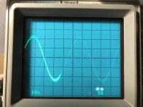
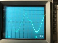
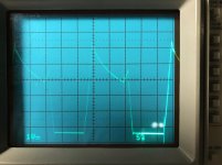
It seems like the amp does not create a signal close to the rails, before part of the positive signal seem to get inverted. I observed this on both outputs, relative to ground. I know there are effectively two channels running in BTL configuration in this amp.
The first picture is before the onset of clipping (I am using a 10x probe) so about 40V peak to peak
The second one is where I am observing the positive portion of the signal inverting, as you can see the negative portion is just before clipping
The third picture is the amp clipping hard and the inversion is still present.
I will have to measure those later tonight when I have a moment, since I do not recall the actual measurements.
Have a look at the output of the amp, this may also be a clue to the problem.
It seems like the amp does not create a signal close to the rails, before part of the positive signal seem to get inverted. I observed this on both outputs, relative to ground. I know there are effectively two channels running in BTL configuration in this amp.
The first picture is before the onset of clipping (I am using a 10x probe) so about 40V peak to peak
The second one is where I am observing the positive portion of the signal inverting, as you can see the negative portion is just before clipping
The third picture is the amp clipping hard and the inversion is still present.
Attachments
Is this the same on both the positive and negative speaker terminals?
If so, is the glitch on the positive half of both positive and negative speaker terminals?
Is the rail voltage solid when the signal dips.
This is sometimes what it looks like when the amp is in current limiting protection.
If so, is the glitch on the positive half of both positive and negative speaker terminals?
Is the rail voltage solid when the signal dips.
This is sometimes what it looks like when the amp is in current limiting protection.
Yes, this is the same on both the positive and negative speaker terminals, relative to the main amp ground.
Yes, both positive half of both positive and negative speaker terminals
I do not know if the rail voltage is solid when the signal dips. I will add this to my list of things to check
This is with no load applied to the output and the amp is pulling about 1.5 amp when this happens. I guess the current limiting protection could be falsely activating up.
I probably just need to get the actual service manual at this point from PacParts instead of trying to reference back and forth between the MRP-M1000 and the MRD-M1005?
My list of things to check
- Measure the op-amp output leading into the PWM section
- Check the positive rail supply when I am observing the output inversion
- Check the over current protection circuit to see if it is activating
- The op-amp leading to the PWM section (IC107) has a clean output of 4V p-p when the output looks like the first picture. One section is non-inverting and the other op-amp is inverting also at the same amplitude. The signal on this op-amp remains distortion free until 8V p-p, when the signal from the op-amp starts to clip gently.
The signal amplitude remains very similar through a 1K resistor (R339 and R340). The signal then the signal pass through an electrolytic capacitor (E301 and E302), still with good signal strength and then through an 8.2K (R301 and R302), to the inverting input of the 2136 (pin2), where it is no longer visible, due to the op-amp action, I assume.
There is also limiting diodes D301 and D302 following the 8.2K to ground, which seem to be performing a limiting action, should the op-amp for some
reason not be able to control the signal on pin 2.
- When the output inverts like observed in the second and third picture, the positive supply remains completely stable.
- I have not looked at the current limiting circuit at this time

- Home
- General Interest
- Car Audio
- Alpine MRP-M650 Strange Behavior, Help needed!