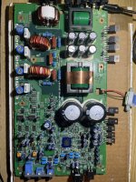
So I just got this amp in, only 2 output mosfets were blown @ Q402 & Q406 (removed all output FETs) 1 of 4 50v/3.3pF caps at E103 was pushed off its lead and leaked, replaced all 4 caps, board powers up, about 1a current pull at idle.
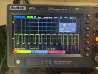
I see a sawtooth and both square waves on the c494GS.
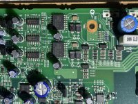
Neither IR2010S show anything other then voltages, no waves of any kind.
No square waves at output sockets and voltages are all over the place at each empty socket, tried figuring out which were high and low but man they are just all screwy, to a layman anyway lol.
Diode “S120” @ D305 near IR2010S (murs120 I think, 200v but 1a or 2a?) is testing bad on DMM. Can’t find anything else wrong/blown.
All 3 resistors @ R404, R405, R406 all look popped, 6.8 from markings, same other 3 diodes @bR410,R411,R412 ran in parallel are at 2.3 as should be.
There’s another post on this board with similar issues, ordering IR2010S and Murs120 chips but which murs120? I’m seeing 1a and 2a versions, I asked a vendor if he could tell by pic of diode and he couldn’t and I can’t find a service manual. I want to replace both IR2010S and the diode at D305 but don’t know it’s exact spec, anyone know?
I see a sawtooth and both square waves on the c494GS.
Neither IR2010S show anything other then voltages, no waves of any kind.
No square waves at output sockets and voltages are all over the place at each empty socket, tried figuring out which were high and low but man they are just all screwy, to a layman anyway lol.
Diode “S120” @ D305 near IR2010S (murs120 I think, 200v but 1a or 2a?) is testing bad on DMM. Can’t find anything else wrong/blown.
All 3 resistors @ R404, R405, R406 all look popped, 6.8 from markings, same other 3 diodes @bR410,R411,R412 ran in parallel are at 2.3 as should be.
There’s another post on this board with similar issues, ordering IR2010S and Murs120 chips but which murs120? I’m seeing 1a and 2a versions, I asked a vendor if he could tell by pic of diode and he couldn’t and I can’t find a service manual. I want to replace both IR2010S and the diode at D305 but don’t know it’s exact spec, anyone know?
Attachments
Last edited:
More current allowed to flow through it? Is current rating not that critical on diodes as long as voltage and package size is onpoint ?
I can’t tell if you’re asking me a question bro or if you’re trying to teach me something 😅 is 1a not that much of a difference to where it won’t effect anything?
I can’t tell if you’re asking me a question bro or if you’re trying to teach me something 😅 is 1a not that much of a difference to where it won’t effect anything?

I’m an idiot, first off the vendor I was searching through can’t be trusted marking same diode just 2 diff auction 1A & 2A (last resort eBay as usual sources out) but ya the current rating changes with temperature ...I really need to start checking data sheets more, which you’ve suggested in the past more then once, ty Perry 😅
Edit: I might have jumped the gun on that answer, pouring over datahseets comparing the 2 now, current seems to lessen as temp goes up. Wish I could find the amps stock diode data sheet to compare
Edit: I might have jumped the gun on that answer, pouring over datahseets comparing the 2 now, current seems to lessen as temp goes up. Wish I could find the amps stock diode data sheet to compare
Last edited:
https://www.vishay.com/docs/88687/murs120.pdf
https://www.vishay.com/docs/88687/murs120.pdf
Same datahseet yet each listed as 1a and 2a on digikey seperately ...ya temp increase lowers current flow from what I can tell. Data sheets man, DATAHSEETS!!!
https://www.vishay.com/docs/88687/murs120.pdf
Same datahseet yet each listed as 1a and 2a on digikey seperately ...ya temp increase lowers current flow from what I can tell. Data sheets man, DATAHSEETS!!!
For some diodes (this one) the part number gives the basic specs. 120 is 1 amp 200v. An MURS220 would be 2 amp 200v. MURS240, 2 amp, 400v. The same thing goes for other part numbers, the ES1D is a 1 amp, an ES2D is 2 amps. The letter suffix gives you the voltage.
Seeing the 2 amp rating for an MURS120 was suspicious.
Seeing the 2 amp rating for an MURS120 was suspicious.
O wow ok, ty Perry that helps a lot 🙂
I've ordered the 3 parts last night that Im going to replace, I’ll report back once I do, should I try/check anything beforehand or in between the removal/install process of the parts? Everything else looks ok, although I haven’t tested any of the BJT transistors yet, but everything else looks good. Think I need to devise probes for my DMM that would make testing them easier (very little space to reach the Base terminal) Im thinking I can test those in circuit and from reverse of board?
I've ordered the 3 parts last night that Im going to replace, I’ll report back once I do, should I try/check anything beforehand or in between the removal/install process of the parts? Everything else looks ok, although I haven’t tested any of the BJT transistors yet, but everything else looks good. Think I need to devise probes for my DMM that would make testing them easier (very little space to reach the Base terminal) Im thinking I can test those in circuit and from reverse of board?
I need to stop being so anxious, sometimes I think I’m working on a human body and the slightest whatever will damage something, if I just slightly bend the components and use my thinner needle probes I should be more then fine. For some reason I had it stuck in my head they needed to be powered on to initially test
Attachments
I replaced the bad 3x 6.8ohm resistors, murs120 diode, and the ir2010s all on same circuit, still no output wave.
I have the output FETs removed still, PS side still functional showing drive/square waves.
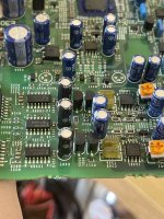
I’m not getting any in/out waves on the 1408BG @ IC305, no in/out waves on either of the 2 14069UG @ IC303&IC304
so I input a low 40Hz 2v amplitude signal from my AWG in the red RCA and you can see a square wave tries to start on all the in/out pins of all the chips all the way to the FET gates, like a rising edge tries but keeps flatlining, I don’t know where to trace the fault back from there, tho.
amps boots up, out of protect I think (what is the light code for rote to on alpine amps? Blinking?) idles at 12v/.7a
I have the output FETs removed still, PS side still functional showing drive/square waves.
I’m not getting any in/out waves on the 1408BG @ IC305, no in/out waves on either of the 2 14069UG @ IC303&IC304
so I input a low 40Hz 2v amplitude signal from my AWG in the red RCA and you can see a square wave tries to start on all the in/out pins of all the chips all the way to the FET gates, like a rising edge tries but keeps flatlining, I don’t know where to trace the fault back from there, tho.
amps boots up, out of protect I think (what is the light code for rote to on alpine amps? Blinking?) idles at 12v/.7a
Attachments
The success rate on these amps is very low. Read through the MRP-M1000 and PDX1.1000 threads to get a start.
Hmm, ya I was reading some even have board internal shorts which are basically impossible to fix, ty for the advice, going to try and trace the signal back as well just to see if I can find the cutoff point where it goes from good to bad, might be a longtime project for learning, I want to be good at Alpine boards, even tho they are so unique like JL/Fosgate designs ...o boy lol.
Ty Perry
Ty Perry
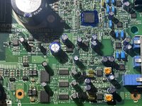
Perry you were right again, reading through the old threads had me thinking I needed a signal ran through this amp to se waves ...once I saw waves on each input/output of the old and new IR2010S I saw this on the low side FET Gates 🙂
Ty sir!
Before I reinstall FETs and put amp back together do you know if this amps high side is fed by the low side like the JL was? Are all Class D amps usually that way? Im going to see what I can find and reread the JL 250/1v2 thread.
Ty sir!
Before I reinstall FETs and put amp back together do you know if this amps high side is fed by the low side like the JL was? Are all Class D amps usually that way? Im going to see what I can find and reread the JL 250/1v2 thread.
Attachments
In the JL, both high and low are driven by the same signal. The high side is made up of discrete transistors. The low side uses the 4427.
This amp uses a signal that comes from the op-amp, to the 4069 where it's split, to the 4081 and then to the 2010 driver.
For most all class D amps, the signal starts from an op-amp that's used for feedback/error correction and then is split to high and low drive signals. The way it's done varies by amp.
Ahh ok, def writing this down as learning the signal&power path as soon as I can is one of my main newb goals, I’m figuring that’s best bet and everything else will fall into place, learning specifics as I go ty Perry.
Also complete succes on this repair, amp is running perfect and the waves look great/clean.
Really appreciate your help with this Perry, thank you 🙂
Also complete succes on this repair, amp is running perfect and the waves look great/clean.
Really appreciate your help with this Perry, thank you 🙂
- Home
- General Interest
- Car Audio
- Alpine MRP-M650 multiple chip failures, need specs