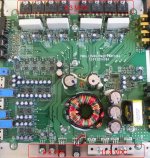
Well I have had this amp for almost 2 years now. One day it just stopped working. Diagnosis: receives power, light turns on, no output to speakers. I tested with different signal inputs and still no output.
I don't know where to get started. A while back a Mr. Perry Babbin helped me with another amp of mine and it worked great. I hope you will see this Perry and help me again. Here are some pics.
http://img155.imageshack.us/img155/2416/dscn1235l.jpg
http://img818.imageshack.us/img818/9669/dscn1237.jpg
http://img98.imageshack.us/img98/274/dscn1238w.jpg
http://img297.imageshack.us/img297/4057/dscn1239.jpg
http://img411.imageshack.us/img411/7721/dscn1240y.jpg
http://img199.imageshack.us/img199/8550/dscn1241m.jpg
http://img231.imageshack.us/img231/1010/dscn1242.jpg
http://img87.imageshack.us/img87/2577/dscn1245.jpg
Last edited:
Does it have both positive and negative rail voltage on the center legs of the output transistors?
are those the big MOSFETS up top of the picture? I just test the center leg with ground with a dmm right?
The transistors in the larger cases are not MOSFETs. They are bipolar transistors. Those are the ones you'll check the voltage on.
Place the black meter probe on the amplifier's ground terminal. Place the red meter probe on the point where you need to measure the voltage.
Place the black meter probe on the amplifier's ground terminal. Place the red meter probe on the point where you need to measure the voltage.
The top transistors are all 9.3v, the bottom left ones are 9.3, and the bottom right ones are 11.3. Refer to the picture for a better look.
Although I did not see any negative polarity. My dmm usually has a neg sign next to the voltage reading. Am I supposed to switch the probes around to check for neg polarity? (Red to ground, black to pin?)
Are these the transistors you were talking about? see below
Although I did not see any negative polarity. My dmm usually has a neg sign next to the voltage reading. Am I supposed to switch the probes around to check for neg polarity? (Red to ground, black to pin?)
Are these the transistors you were talking about? see below
Attachments
What is the DC voltage on the first leg of the power supply FETs? They are the 4 transistors with 11.3v on the center leg.
Actually the power FETs are 11.6v all around not 11.3v. I take it the first leg is the very left one looking at it from the picture I posted. All FETs show 0v exactly and to make sure I also checked the other legs as well (the very right ones) and they were 0v as well.
Also, the other transistors I originally checked also have a negative polarity of 9.3v all around.
Also, the other transistors I originally checked also have a negative polarity of 9.3v all around.
Post the DC voltage for each pin of the driver IC (..494). Place the black meter probe on the amplifier's ground terminal. Place the red meter probe on the point where you need to measure the voltage.
IC#
Pin 1:
Pin 2:
Pin 3:
Pin 4:
Pin 5:
Pin 6:
Pin 7:
Pin 8:
Pin 9:
Pin 10:
Pin 11:
Pin 12:
Pin 13:
Pin 14:
Pin 15:
Pin 16:
IC#
Pin 1:
Pin 2:
Pin 3:
Pin 4:
Pin 5:
Pin 6:
Pin 7:
Pin 8:
Pin 9:
Pin 10:
Pin 11:
Pin 12:
Pin 13:
Pin 14:
Pin 15:
Pin 16:
Post the DC voltage for each pin of the driver IC (..494). Place the black meter probe on the amplifier's ground terminal. Place the red meter probe on the point where you need to measure the voltage.
IC#
Pin 1: 8.1
Pin 2: 2.43
Pin 3: 4.51
Pin 4: 3.94
Pin 5: 1.4
Pin 6: 3.59
Pin 7: 0
Pin 8: 11.56
Pin 9: 0
Pin 10: 0
Pin 11: 11.56
Pin 12: 11.56
Pin 13: 4.9
Pin 14: 4.9
Pin 15: 2.43
Pin 16: 0.04
Power up the amp and check for DC on the third leg of the output transistors. Do any have more than a fraction of a volt of DC on them?
All power FETs have 0v at leg 3 on the 200m level which is the lowest my dmm goes. There is also 0.1v on leg 1 however. I also noticed that there is 1.9v running when I probed the case. Does that mean there is a minor short somewhere? Remember all these readings are in the 200m range.
Is it correct that you previously had both positive AND negative voltage on the center legs of the various output transistors?
Do you have both positive and negative voltage on the small 8 pin op-amps (pins 4 and 8)?
Do you have both positive and negative voltage on the small 8 pin op-amps (pins 4 and 8)?
Well Perry we found the culprit. One of the main copper lines fried apart. Theres a good 2 inches of the circuit that has peeled off the board. Looks like the circuit from the transformer.
The last pictures shows it really well.
http://img801.imageshack.us/img801/4002/dscn1250n.jpg
http://img408.imageshack.us/img408/8227/dscn1251.jpg
http://img693.imageshack.us/img693/6599/dscn1256r.jpg
http://img149.imageshack.us/img149/5273/dscn1257t.jpg
The amp has overheated in the past at least 10 times no more than 20 tho. It has overheat protection because it shuts off when it gets hot and turns back on after a minute or two. Could this be the problem? Is this even repairable? I was thinking of running a piece of wire from beginning to end and bypass all the discolored and burnt spots.
Last edited:
- Status
- Not open for further replies.
- Home
- General Interest
- Car Audio
- Alpine MRP-F300 amp is dead, need help with repair