The waveforms on the outputs should have been referenced to the reference line. The waveforms you posted look like a single probe on DC coupling.
@10v/div, they do. Should they stay on the ref line no matter the voltage/div? I see the picture shows 20v/div.
Are you setting both channels the same when it deflects up/down?
As long as they are the same, they should remain on the reference. The only difference will be the amplitude above or below the reference.
As long as they are the same, they should remain on the reference. The only difference will be the amplitude above or below the reference.
I am, both channels are set up the same. I can set inv. probe to 12v and it drops below ref line and normal to 12v and it deflects up. I place both probes on 12v no deflection, stays at ref.
If you set both channels to 5v/div and check 12v or the source/gate of the outputs, do you get deflection?
I know that this may seem like a lot of work but after you get it right, it makes the scope much more useful.
I know that this may seem like a lot of work but after you get it right, it makes the scope much more useful.
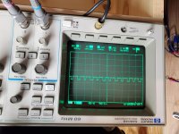

This is better. When displaying waveforms, set the scope to display 3-4 cycles and set the vertical amplifier so that the waveform covers approximately 3 major divisions vertically.
No need to repost. Just an FYI.
With a mains powered scope, you cannot measure drive signals referenced to the rails with DC coupling and good resoolution. This setup give you the ability to view those waveforms with high resolution.
The scope can remain like this. If you're doing standard tests, you can use only the normal probe.
- Home
- General Interest
- Car Audio
- Alpine MRD-M500