Hey.
I'm having problems with MRD M1005.
Amp turns on fine but output section is quiet.
I'm pretty sure the pre amp section works fine because input signal reaches IC301/302. Tho for some reason IC301 seems to have weaker signal, but works. Both IC's put out pwm.
Weird thing is i'm missing VDD on all the output IC's
(IR2010 drivers and IC 303,304,305)
When VSS is -37.7v then VDD is(on the ic's) -35.7v.
I did find that Q306 had failed and was open all the time.
I replaced that but nothing changed.
Been messing with this thing for 2 weekends with no results.
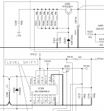
I'm also uploading the schematic for this because it's available online.
If anyone has suggestions or can tell me what im missing i'd be really grateful.
I'm having problems with MRD M1005.
Amp turns on fine but output section is quiet.
I'm pretty sure the pre amp section works fine because input signal reaches IC301/302. Tho for some reason IC301 seems to have weaker signal, but works. Both IC's put out pwm.
Weird thing is i'm missing VDD on all the output IC's
(IR2010 drivers and IC 303,304,305)
When VSS is -37.7v then VDD is(on the ic's) -35.7v.
I did find that Q306 had failed and was open all the time.
I replaced that but nothing changed.
Been messing with this thing for 2 weekends with no results.
I'm also uploading the schematic for this because it's available online.
If anyone has suggestions or can tell me what im missing i'd be really grateful.
Attachments
Did Q306 shorting drive high voltage to the logic ICs?
I know that you said it opened but it may have shorted before it opened.
I know that you said it opened but it may have shorted before it opened.
Last edited:
Do you have a scope?
Please (and this applies to anyone who needs repair help) use your sig line to list all equipment you have, editing it as equipment changes. Include the model numbers.
Top of page, menu USER CP >> EDIT SIGNATURE
Oscilloscope (yes or no)
Multimeter(s)
Type of signal source (grounded RCA shields preferred).
Soldering iron
Desoldering pump
Power supply
2 ohm current limiting resistor (hollow cylindrical ceramic 100w preferred)
For IC303, what's the DC voltage across terminals 7 and 14?
If you drive a signal into the amp, do you see a square wave on any of the terminals of that IC?
If you drive a signal into the amp, do you see a square wave on any of the terminals of that IC?
Pin 7 reads -36.5V and pin 14 reads -34.5V measuring from gnd.
Using phone as a source i need to turn up the gain(to 0.3v or so)
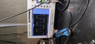
I have square wave on pins 1, 2, 3, 4, 5, 6, 10, 11, 12 and 13.
Using phone as a source i need to turn up the gain(to 0.3v or so)
I have square wave on pins 1, 2, 3, 4, 5, 6, 10, 11, 12 and 13.
Try with black probe on 7, red on 14.
It should be about 12v.
What's the DC voltage across B+ and ground terminals?
It should be about 12v.
What's the DC voltage across B+ and ground terminals?
Black probe on 7 and red on 14 i'm reading 2V exactly.
If by B+ and gnd you mean 12v input then i'm feeding it with 11.5V at the moment.
If by B+ and gnd you mean 12v input then i'm feeding it with 11.5V at the moment.
The rail voltage is lower than the service manual shows it to be but that may be because the SM uses 14.4v.
You'll see that there is an error in the diagram for the Zener on Q306. What's the DC voltage across the Zener that's connected to the base of Q306?
You'll see that there is an error in the diagram for the Zener on Q306. What's the DC voltage across the Zener that's connected to the base of Q306?
Further testing will be done on 14.4V
But hey, that zener is dead. Took it off the board and reads 39ohms both ways. Do you know the value of that zener Perry Babin?
But hey, that zener is dead. Took it off the board and reads 39ohms both ways. Do you know the value of that zener Perry Babin?
Thanks a lot! Now i have my 12v back between vss and vdd.
But theres more to come. When applying input signal the current consumption jumps to ~3A and stays there until i unplug the remote. Seems like im missing gate drive on one channel. I need to leave for work for the week so i'll be looking into this next weekend. I will try to grab new drivers for testing too.
Do you happen to know if the output section will turn on without fets installed, Perry?
Many thanks again!
The diagram below is for a different IC but the tests are the same. For the most part, you want to compare the readings from the two output terminals of each IC to their corresponding power supply terminals.
The two ICs should read the same.
Do you have good square waves feeding the Hin and Lin of both ICs?
The two ICs should read the same.
Do you have good square waves feeding the Hin and Lin of both ICs?
Attachments

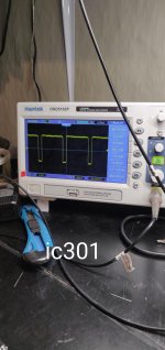
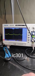
On IC308 i have both Hin and Lin. On Ic307 i have neither except when i turn the gain really high(1V and less) then square wave appears. I currently have fets removed and im only getting Hout on Ic308, ic307 output is silent even with gain maxed. Im adding pics of the opamps(301/302). On ic301 in and out signal is quite a bit different compared to ic302. Also ic301 wont turn on with small signal, gain needs to be pretty high.
I dont get it where the signal disappears on ic301. Because i have nice sinewave on both R340/R341
I dont get it where the signal disappears on ic301. Because i have nice sinewave on both R340/R341
Attachments
I did and nothing seems to be wrong. All readings on both drivers look identical and are in mega ohms.
Last edited:
At the point where you have signal on only IC308, how do the signals compare on pin 1 of IC303 and IC304?
- Home
- General Interest
- Car Audio
- Alpine MRD-M1005 no output