I'm trying to build a supply for a project with the aim of gettinat least 60mA at anywhere over 180V. I think the upper limits here would be more dictated by component availability and cost than by anything else. I started with an unregulated supply, which works just fine, but ideally I would want a regulated supply - the load can vary a lot, so a regulated supply would make the rest of the circuitry a lot simpler.
Once I discovered VR tubes, I decided that an all-tube regulator would be the way to go because, well, I like glowing things! I don't need anything very fancy - this is not an audio application and the powered circuitry can handle a little ripple. I'm looking at your basic VR+Error+pass tube design.
So, to my questions:
1. What determines the power rating of the supply? For example I have seen designs that use the 6BM8, but they don't meet my current requirements. I've also seen a design that uses a 6080(?) pass tube, but that seems a bit of a hog when it comes to the heater current.
2. Does the heater of the pass tube have to be isolated from other heater supplies? The designs I've seen sometimes state this as a requirement, but I can't find an explanation as to why.
3. Can anyone recommend a transformer for this application? As usual, the transformer seems to be the hardest part to source, so if there is a boiler-plate design that includes an off-the-shelf transformer, that would make life a little easier.
Here is some good reading: Tube Based Voltage Regulators - Part 1STEVE BENCH site mirror by JACMUSIC
I'm trying to build a supply for a project with the aim of getting at least 60mA at anywhere over 180V.
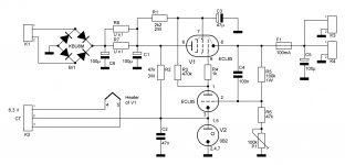
ECL85 would be sufficient. I have built several power supplies with this tube.
What determines the power rating of the supply?
Pass tube. Mainly it's Ik (max.) and Pa (max.)
Does the heater of the pass tube have to be isolated from other heater supplies?
Yes, it requires own heater winding. This must also be biased so that max. heater-cathode voltage will not be exceeded. For ECL85 this is 100 Vdc.
Attachments
Can anyone recommend a transformer for this application?
This has several heater secondaries:
TSL 100/001 INDEL - Transformer: mains TSL100/001 | TME - Electronic components
An externally hosted image should be here but it was not working when we last tested it.
Please keep in mind that glow discharge voltage reference tubes have an ignition voltage that's higher than the maintaining voltage and that they have an unpredictable ignition delay. See also Glow tube response rate
Last edited:
Edcor sells suitable power transformers. (The OP is here in the U.S.)
Given the low desired output voltage target I would probably replace the 0B2 with a zener diode, 60V or thereabouts.
I would sooner use a higher voltage. Higher is OK, 180V is the minimum.
Thanks Artosalo. I created a LTSpice simulation with my expected loads and my rectification stage and that circuit works well.
I would like to get some opinions on a way to go with transformers. I am using a 6CA4 rectifier tube in my rectification a stage, so I need another 6V3 winding for that. My simulation also shows I need at least 500V CT. However off-the-shelf transformers with 500V CT and 2x6V3 CT are few and far between. Hammond make one with 550V CT secondary, but the current rating is only 75mA, which doesn't leave much headroom. It looks like 500V/5V/6V3 is a lot more common, but then I'd need to switch to a rectifier like the 5AR4. Or I could also buy a dedicated 6V3 filament transformer.
So, I am plagued with indecision. There isn't much to choose between these options, so if anyone has strong opinions, I would appreciate the input.
BTW, I know I could use diodes rather than a rectifier tube. I'd just prefer not to.
Thanks Artosalo. I created a LTSpice simulation with my expected loads and my rectification stage and that circuit works well.
I would like to get some opinions on a way to go with transformers. I am using a 6CA4 rectifier tube in my rectification a stage, so I need another 6V3 winding for that. My simulation also shows I need at least 500V CT. However off-the-shelf transformers with 500V CT and 2x6V3 CT are few and far between. Hammond make one with 550V CT secondary, but the current rating is only 75mA, which doesn't leave much headroom. It looks like 500V/5V/6V3 is a lot more common, but then I'd need to switch to a rectifier like the 5AR4. Or I could also buy a dedicated 6V3 filament transformer.
So, I am plagued with indecision. There isn't much to choose between these options, so if anyone has strong opinions, I would appreciate the input.
BTW, I know I could use diodes rather than a rectifier tube. I'd just prefer not to.
The Hammond transformers I looked at don't have enough current on one of the 6V3 secondaries. They do have a 550/6V3/5 transformer in both regular and potted versions, but the filament secondaries are not CT.
Just use another 6V3 transformer? Or make a "fake" centre tap with 2x100R
Check out Hammond 167 series: Hammond Mfg. - Power Transformer - (167 Series)
Check out Hammond 167 series: Hammond Mfg. - Power Transformer - (167 Series)
There is a very interesting article relationed to power supplies of this kind in the Wireless World magazine since 1948, wrote by a guy called Scroggie. Google for it in american radio history.com (THE HISTORY OF RADIO documented in thousands of PDF books and magazines). Very good source from David.
@kodabmx: I was wondering if there was some way to create an artificial center tap. Thanks very much for that info. The situation with the hammond transformers is more complex than I thought. They have three series, 200, 300 and 300P. There are equivalent transformers in each series, except the 200 series versions don't have the 6V3 CT. The 300 and 300P ones do. I'm very tempted by the potted version, but then it is about three times the price of the 200 version. I also need to work through the circuit with a 5AR4 to make sure I'm not missing something. I don't want to drop $230 on a transformer only to discover the circuit I want to use it in doesn't work!
@Osvaldo: This is the link? https://www.americanradiohistory.com/Archive-Radio/40s/Radio-1947-02-03.pdf
@Osvaldo: This is the link? https://www.americanradiohistory.com/Archive-Radio/40s/Radio-1947-02-03.pdf
No need for a heater winding CT in this circuitry!
Best regards!
In artosalo's cifcuit? Please explain. The ECL85 data sheet seems fairly clear on this.
You can simply supply a suitable "bias" voltage to one heater pin. Do you need a schematic as an example?
That would be great. Thanks.
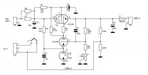
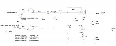
Here is modified schematic. Now the heater transformer does not have CT, only single 6,3 V winding.
The output voltage of the regulator is 300 Vdc and we want to bias the ECL85 heater to some 200 Vdc.
We get this voltage with two resistor voltage divider (100k and 220k) and feed it to either one heater pin.
The voltage divider can also be before the pass tube.
The output voltage of the regulator is 300 Vdc and we want to bias the ECL85 heater to some 200 Vdc.
We get this voltage with two resistor voltage divider (100k and 220k) and feed it to either one heater pin.
The voltage divider can also be before the pass tube.
Attachments
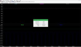
I've been simulating the power supply in LTSpice using the Ayumi tube models, and I am concerned about the current being drawn through the transformer. I was planning on using a transformer rated for 100ms or 144ms, however the peak current shown by LTSpice is around 224mA (actually -224mA, why is that?). The RMS current is 75mA. I've attached the circuit and a run of that circuit.
Would either of the transformers be OK with this peak current draw?
Would either of the transformers be OK with this peak current draw?
Attachments
Take a look to my solution at
High (Audio) Quality AM Tuner - diyAudio
post 107 and others. Perhaps they may be a guidance for you.
High (Audio) Quality AM Tuner - diyAudio
post 107 and others. Perhaps they may be a guidance for you.
- Status
- This old topic is closed. If you want to reopen this topic, contact a moderator using the "Report Post" button.
- Home
- Amplifiers
- Power Supplies
- All-tube regulated power supply