I searched a lot for it, but I've been not able to find a schematic of an all-tube CCS.
I mean, I would like to understand if it is possible, in an easy way, to realise a CCS only with tubes, and use it for a parallel feed stage.
Ciao,
Giovanni
I mean, I would like to understand if it is possible, in an easy way, to realise a CCS only with tubes, and use it for a parallel feed stage.
Ciao,
Giovanni
croccodillo said:I searched a lot for it, but I've been not able to find a schematic of an all-tube CCS.
You're missing the forest for the trees 🙂 You are looking for a complex schematic when all you will see in actuality is single pentodes used as CCS's. Look through your schematics again looking for examples of, for example, 6EJ7 under a differential pair and this will be more obvious.
Well, that depends. It's one thing to have a pentode CCS UNDER a long-tail pair, and another to have the CCS OVER the tube as a plate load. When a CCS is a two-terminal ("self-biasing") device like a FET with a resistor, it can be used either "under" or "over". But a pentode CCS may not be a mere two-terminal device because there may be external biasing connections for the screen. The pentode's plate looks like a CCS, but the cathode end may not, unless we allow the kind of complications that Pimm has apparently mastered.
Brian Beck said:Well, that depends. It's one thing to have a pentode CCS UNDER a long-tail pair, and another to have the CCS OVER the tube as a plate load.
Using a pentode as a CCS over another tube makes a Kimmel Mu Stage.
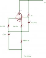
This is the Pentode CCS I used.
The bias is set by the bias resistor and is dependent on the pentode used and the current required.
The stiffening resistor stiffens the action of the CCS and burns up any excess voltage which isn't needed for the loaded triode. It can be left out.
This can be used as a MU-stage, but I chose not to do this as it will compromise linearity. I took the output from the triode plate.
Hope that helps.
Shoog
Attachments
Thanks for your answers, but, as told, the pentode CCS is not the best solution, I think.
Using a CCS in a parafeed means that the CCS must be linear, and must handle "big" currents.
The only way to achieve this is to add negative feedback to the CCS, and thus control its output current.
I was thinking to something like THIS , where the V2 tube is a 6SN7 tube, that can go down to near 0V between the plate and the cathode.
The only drawback is that we need two more floating power supply voltages for each CCS (+100V, -100V).
But this can simply been solved using a 5W transformer with a double 115+115V primary winding and a 9V secondary output, using it inverted and feeding 6V to the secondary: at the primary you'll find about 75V, that rectified become about 100V.
The current sense resistor (R2) feeds the V2A triode, and thus change the plate voltage from 0V (center) to something near + 100V.
The voltage swing will drive the V2B triode, allowing the output triode (KT88) grid to move from 0V to -80V, more than enough for our application.
Your comments?
Ciao,
Giovanni
Who said that the pentode CCS wouldn't be linear. I said that if you used it as a MU-stage it would compromise its linearity - this is because the output transformer is in parallel with the cathode resistor, and the output transformer is non-linear. Also in your parafeed arrangement, lowering the output impedence beyond a certain point will mean that you will need to increase the size, and cost, of your parafeed cap.
I believe a single Pentode CCS will be quite adequate of itself. However better results can be had by using Gary Pimms basic pentode CCS. There are no additional Mosfets and just a simple voltage reference chip. This will produce excellent results and is elegantly simple.
Shoog
I believe a single Pentode CCS will be quite adequate of itself. However better results can be had by using Gary Pimms basic pentode CCS. There are no additional Mosfets and just a simple voltage reference chip. This will produce excellent results and is elegantly simple.
Shoog
- Status
- Not open for further replies.
- Home
- Amplifiers
- Tubes / Valves
- All tube CCS