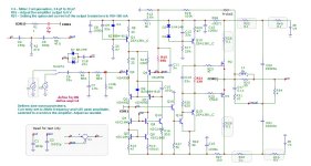
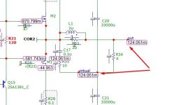
Hi, colleagues!Further improvement by changing the input stage to virtual earth, decreasing the "varactor effect" substantially.
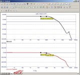
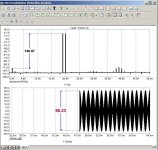
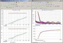
I’ve improved the input stage of the amplifier by adding a tracking power supply to the comparison node. The results are shown in the images below. I see no reason to modify the second stage— even if the actual distortions are 100 times worse, the harmonics at 20 kHz with 116 W (4 Ω) output will still be below 0.001%. At other power levels and frequencies, the distortions will be even lower.

Hello, friends.
I have significantly modified the amplifier output to prevent large currents from flowing through the GND terminals, resulting in a safer configuration for the speakers. The load now sees no DC offset. This approach requires one pair of large capacitors for each amplifier board — typically four capacitors in total, which is common in traditional designs. I don't think this will pose any problem.
The circuit also includes “parasitic resistors” and other components that are either unnecessary or subject to debate. My primary interest here was to study compensation networks to ensure amplifier stability.
This setup is intended for experimenting with different design ideas and optimizations.
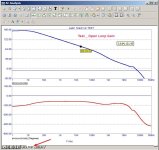
The main simulations are already configured — see the attached screenshots. Feel free to tweak and explore further.

I have significantly modified the amplifier output to prevent large currents from flowing through the GND terminals, resulting in a safer configuration for the speakers. The load now sees no DC offset. This approach requires one pair of large capacitors for each amplifier board — typically four capacitors in total, which is common in traditional designs. I don't think this will pose any problem.
The circuit also includes “parasitic resistors” and other components that are either unnecessary or subject to debate. My primary interest here was to study compensation networks to ensure amplifier stability.
This setup is intended for experimenting with different design ideas and optimizations.
The main simulations are already configured — see the attached screenshots. Feel free to tweak and explore further.
Attachments
-
 MC12 SH.jpg149.4 KB · Views: 48
 -
 AF 1.jpg71.5 KB · Views: 11
 -
 OUT 0dc.jpg31.6 KB · Views: 14
 -
 IMD 19_20khz.jpg90.5 KB · Views: 16
 -
 HD 0dc.jpg146.7 KB · Views: 12
 -
 ST1.jpg141.7 KB · Views: 15
 -
 ST2.jpg67.1 KB · Views: 15
 -
 TA mosfet.jpg96.5 KB · Views: 13
 -
 TA OUT clip.jpg70 KB · Views: 14
 -
 test OLG.jpg76.7 KB · Views: 13
 -
Test only.rar25.7 KB · Views: 8