Thank you Jan,
but I hope that this thread will not become a continuation of the dispute. On the contrary, I would very much welcome it if "Bernhard" could let off steam here - and bring MC12 closer to us old SPICE users and make it palatable.
This is the opportunity to set up a tutorial or to clarify all questions regarding MC12.
Best regards,
HBt.
Hello MC12 users!
What AC analysis settings are convenient for estimating amplifier parameters?
What source resistance should be used for testing?
MC12 is a tool, the question is how to configure it for maximum process visibility and display of results.
Interesting things:
The parameters of resistors and capacitors can be specified using expressions.
r(r22) - resistance corresponds to (r22) c(c1)/2 - capacity corresponds to the expression c1/2
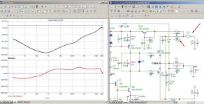
My simple amplifier design demonstrates a THD of less than 0.0001% for 20KHz
Too optimistic. There is a high probability that there are some errors with the data settings for MC12.
I would be grateful if you could tell me where to correct the settings.
For now, a few pictures and a file of the amplifier itself for MC12.
Too optimistic. There is a high probability that there are some errors with the data settings for MC12.
I would be grateful if you could tell me where to correct the settings.
For now, a few pictures and a file of the amplifier itself for MC12.
Attachments
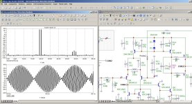
Two-tone input signal 19+20 kHz 1:1, maximum output amplitude before clipping.
In the audio range, the difference signal at 1 kHz is 140 dB lower than the main tones
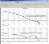
The circuit is very simple, nothing “super”, the “loop gain” at 20 kHz is 60 dB only.
Where is my mistake?


In the audio range, the difference signal at 1 kHz is 140 dB lower than the main tones
The circuit is very simple, nothing “super”, the “loop gain” at 20 kHz is 60 dB only.
Where is my mistake?
Loop gain at 20k is higher because the compensation network includes the output devices so is a feedback loop within the global feedback loop. With mosfets this doesn't have adverse effects on stability. The topology can even be extended by changing Q6 to a cascode with high gain device like MPSA18 "below" and the 2SC3503C "on top". Further improvement by changing the input stage to virtual earth, decreasing the "varactor effect" substantially. So I don't think something is wrong with this sim. The disadvantage of such a simple topology is PSR which in relation to distortion products at the output is a few orders of magnitude too low

It's not your fault. The models that any simulator uses are not exactly the same as the real world part. Many models do not correctly model the non-linearities, so the distortion results cannot be trusted. In general, simulator reported distortions are much, much to optimistic.
Other limitations are that sometimes the internal parasitics are not correctly modeled so the circuit works fine in the sim but oscillates in real world. Or vice versa.
Edit: most users do not include real world wiring inductances and capacitances and that can also have a large impact on how realistic the simuation results will be.
Also, you cannot blow up a part in the sim from too much heat but you can in real world!
Jan
Last edited:
Actually, uCap can produce a stability analysis suggesting the amp is OK whereas transient analysis with sufficient resolution shows VHF oscillation. The question mark here is "wiring". It has been discussed a while ago also related to an amp with unlikely low distortion so is was measured which also showed that contrary to ucap sim, the actual circuit did not oscillate. See
https://www.diyaudio.com/community/threads/musings-on-amp-design-a-thread-split.366099/page-61 and further
https://www.diyaudio.com/community/threads/musings-on-amp-design-a-thread-split.366099/page-61 and further
I can hardly contribute anything productive here, my gut feeling keeps telling me to be very careful with MC's euphoric results.
Thanks for the link Aridance, I had followed the technical discourse with great interest at the time, but the usual dissent was very sad - we have to filter that (out).
Thanks for the link Aridance, I had followed the technical discourse with great interest at the time, but the usual dissent was very sad - we have to filter that (out).
hbtaudio, your gut feeling is in the proper direction: measurement of actual amps generally produces more distortion than suggested by a sim. The most overlooked issue is PSR so the power supply (Ri) can have a large effect. Sim results will be more "in line" with measurements if you add an R of 0.1 ohm to each supply source. The rails can be decoupled with the usual caps of a few 100 uF plus ceramic Cs or equivalent for RF decoupling. A 100+100 W stereo at full power (8R speakers) then can result in up to 1V over the Ri and with PSR (just) 60 dB that's 1 mV at the output. With ~40Vp signal at the output and THD -120 dB that's 40 uV THD - the issue, added distortion via modulation of the power supply, might be clear no?
Thanks for the answer.The topology can even be extended by changing Q6 to a cascode with high gain device like MPSA18 "below" and the 2SC3503C "on top". Further improvement by changing the input stage to virtual earth, decreasing the "varactor effect" substantially. So I don't think something is wrong with this sim.
The circuit is interesting in its simplicity and there is no point in complicating it with a cascode. IMHO
Although, I must admit, the cascade is excellent, and fast (which is important at this stage of amplification).
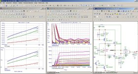
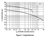
Regarding the “varactor effect” - the deviation of the BC voltage on transistors Q1Q2 is about 3 V, with an average voltage value of about 40 V. This is at the maximum output voltage (limit value).
This transistor mode has minimum transient capacitance at 40V, and a small excursion (3V) will result in minimal change in capacitance. Judging by the graphs in PDF.
I hope I'm not wrong.
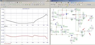
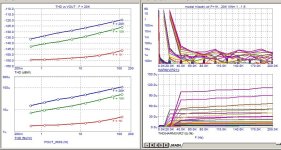
Analysis showed that you completely right.The disadvantage of such a simple topology is PSR which in relation to distortion products at the output is a few orders of magnitude too low
The ideal solution to this problem is to use OPAM at the first stage of the amplifier. Or need separate the output stage and use two power supplies.
I tried to apply simple filters, I attach the graphs.
Perhaps you have a better solution or idea?
Attachments

I understand and accept this. Thank you.Edit: most users do not include real world wiring inductances and capacitances and that can also have a large impact on how realistic the simuation results will be.
Also, you cannot blow up a part in the sim from too much heat but you can in real world!
Jan
Design, layout, PCB design, poor proximity, long connections. These little things add up to stability problems.Actually, uCap can produce a stability analysis suggesting the amp is OK whereas transient analysis with sufficient resolution shows VHF oscillation.
The higher the gain within the circuit, the more problems there are.
The simple topology has 2 places with high Z: the output of the diff amp and the VAS (mosfet driver). High impedance doesn't combine well with varactor effect (even if small), hence the use of cascode makes a noticeable difference. With the proper devices a cascoded VAS can produce ~100 dB gain and the surplus allows more NFB. A simple way to address PSR is to use a single supply topology, allowing for 120dB or more. GNFB can be split in a DC component for operating point and AC component that includes both input and output C. Compared to the dual supply alternatives in my amp libs the choice to build it already has been made. An additional argument is that simulation suggests a better performance than that of the OPA552 based amp in the other thread and there isn't a 60V limit. Another difference with the opamp version is higher slew rate. The input R of a virtual earth stage can be split in two with C to ground at the center. The first RC is to prevent saturation (with square wave input) and the second RC is part of the compensation, which for an opamp has to be set to a value that doesn't exceed Amin. Because all of that is part of the GNFB loop the overall response can be very flat and at full power IMD sims below -140 dB (19 & 23 k).
Hello,
My search has brought me here, I am looking for a red led model in Microcap12 however browsing from the library has given me numerous models. I could not define which one of them would be a good alternative for a 5mm red led. The kind that we always use for current source of the input LTP. There are animated leds but it does not says much about its specs.
Thanks!
Hello,
MicroCAP is still showing the replaced model of the device as a reference when you hover the mouse above. I tried to delete the unused models in the models tab, nothing happened. Also tried running cleanup command still nothing happened. How do I correct this?
Thanks!
MicroCAP is still showing the replaced model of the device as a reference when you hover the mouse above. I tried to delete the unused models in the models tab, nothing happened. Also tried running cleanup command still nothing happened. How do I correct this?
Thanks!
Attachments
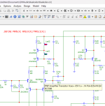
Try applying the data from the gurus of radio electronics modeling Bob CordellHello,
My search has brought me here, I am looking for a red led model in Microcap12 however browsing from the library has given me numerous models. I could not define which one of them would be a good alternative for a 5mm red led. The kind that we always use for current source of the input LTP. There are animated leds but it does not says much about its specs.
Thanks!
SPICE MODEL Cordell
* LEDs
*
- BLUE LTL1CHTBK4
- GREEN LTL1CHKGKNN
- RED LTL1CHKEKNN
- BLUE LED Lite-on LTL1CHTBK4
- created November 23, 2010 copyright Cordell Audio
*
*
- GREEN LED Lite-on LTL1CHKGKNN
- created November 23, 2010 copyright Cordell Audio
*
*
- RED LED Liteon LTL1CHKEKNN
- created November 23, 2010 copyright Cordell Audio
- Home
- Design & Build
- Software Tools
- All about MicroCap12