Is this a guitar amp?
No,
that sign was what came closest to an RCA.
Looks wasteful. You only gain 3dB over using a single pair per channel. Consider getting more efficient speakers or use a different tube. My $.02
Looks wasteful. You only gain 3dB over using a single pair per channel. Consider getting more efficient speakers or use a different tube. My $.02
Having already valves, transformers and chokes it is inexpensive.
With a pair you can get just over 3-4w ... with efficient loudspeakers they could be enough.
Last edited:
I asked about the possibility of it being a guitar amp because gain will be rather high. The 27K plate load resistor on 6EM7 section 1 won't work well unless you are paralleling multiple sections.
I asked about the possibility of it being a guitar amp because gain will be rather high. The 27K plate load resistor on 6EM7 section 1 won't work well unless you are paralleling multiple sections.
the total gain is 130 ... we should decrease Ra too much and I doubt that it would work well ... we could betray the mono-tubes project and use something like an hall of 12AU7 or use the second section as CF, something for which that valve it is naturally brought ... what do you say?
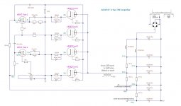
So, the first thing I would do is run the max voltage on section 2. Aim for 400V of B+, run 30mA of current, then you'll be just under idle dissipation with the cathode bias voltage and output transformer voltage drop factored in.
This extra voltage will help properly load the first stage. You can use a 100K plate load and a 1K bias resistor to get you about 2mA of current and 200V on the plate. Since you have so many extra section 1 triodes, you could parallel two for the first stage and run a 50K plate load and a 500 ohm bias resistor for two sections.
For the other two sections 1 triodes you would have, parallel them into a cathode follower. You could run quite a bit of current through them according to the datasheet, you just have to keep the dissipation down. These can be directly coupled to the first stage, and a 20K-35K cathode resistor for the cathode follower will do nicely. It will be biased up a bit above 200V DC, so elevate the tube heaters to +50V to account for that.
Now you've used four 6EM7s and you've used both sections in all tubes. The last question is whether the ~1250 ohm load works for four tubes. It doesn't look all that great unfortunately, so perhaps aiming for the middle is a better plan. B+ around 300V for a plate to cathode voltage of 250V on the output section. Run them at 40mA each so you can get all the juice out that you need. A 100K plate load on the driver with a 1.3K cathode resistor will work OK for a single driver triode, or 47K/650 for paralleld triodes up front.
Why would you turn the 100's around? The polarity looks good. Negative ends all go to ground, and positive ends go to voltages above ground. Seems okay to me.
The schematic in #1 was reposted and corrected so its now correct within the 1/2 hour window. So ignore my comment #2 as I did not remove it quick enough.
Last edited:
So, the first thing I would do is run the max voltage on section 2. Aim for 400V of B+, run 30mA of current, then you'll be just under idle dissipation with the cathode bias voltage and output transformer voltage drop factored in.
This extra voltage will help properly load the first stage. You can use a 100K plate load and a 1K bias resistor to get you about 2mA of current and 200V on the plate. Since you have so many extra section 1 triodes, you could parallel two for the first stage and run a 50K plate load and a 500 ohm bias resistor for two sections.
For the other two sections 1 triodes you would have, parallel them into a cathode follower. You could run quite a bit of current through them according to the datasheet, you just have to keep the dissipation down. These can be directly coupled to the first stage, and a 20K-35K cathode resistor for the cathode follower will do nicely. It will be biased up a bit above 200V DC, so elevate the tube heaters to +50V to account for that.
Now you've used four 6EM7s and you've used both sections in all tubes. The last question is whether the ~1250 ohm load works for four tubes. It doesn't look all that great unfortunately, so perhaps aiming for the middle is a better plan. B+ around 300V for a plate to cathode voltage of 250V on the output section. Run them at 40mA each so you can get all the juice out that you need. A 100K plate load on the driver with a 1.3K cathode resistor will work OK for a single driver triode, or 47K/650 for paralleld triodes up front.
First of all I made a mistake in the thread header because 6EA7 is similar to 6EM7, but not the same.
I took those tubes into consideration because they are ductile enough, and because I have a transformer powerful enough to drive those currents and I can get no more than 240v DC from it.
I also have another transformer whose data I don't know and which delivers 205v AC without load. I don't think it can drive all that current though, so I should use no more than 3 tubes in parallel.
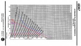
In standard configurations 6EM7 works at 250v first section, 150v second section, with 330v max. It seemed to me that a good compromise could have been to work both around 200v, and this could be in line with my transformer.
Your idea of using at least 16 of the 20 triodes present in the tubes is very fascinating ... do you think it can also be done with 200v, even if this could require substantial compromises?
The calculation OT I did using the chart that I have attached.
What I definitely forgot was considering the drop on OT.
Attachments
The schematic in #1 was reposted and corrected so its now correct within the 1/2 hour window. So ignore my comment #2 as I did not remove it quick enough.
thanks anyway for letting me know.
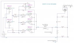
Something similar?
Or better to use the 2 triodes for the CF?
Or better to use the 2 triodes for the CF?
Attachments
Last edited:
I think the others were suggesting making the cathode follower parallel rather than the input stage. You will have lower gain now which is much better for your application. The plates of the cathode follower can come off the main supply if you prefer.
Last edited:
I think the others were suggesting making the cathode follower parallel rather than the input stage. You will have lower gain now which is much better for your application. The plates of the cathode follower can come off the main supply if you prefer.
to come off, in which sense?
Sorry very poor explanation - you could take the plate of the cathode follower directly from main HT rather than the dropper resistor. The cathode follower has good rejection of the voltage on the plate. However there's no advantage over doing this so I don't know why I said it!
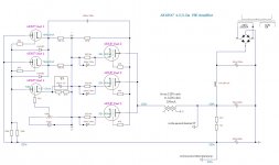
I think having two unit 1's in parallel for the cathode follower instead of the first stage means you can run more current through the second stage where its needed. I think that was what Audiowize is suggesting.
I think having two unit 1's in parallel for the cathode follower instead of the first stage means you can run more current through the second stage where its needed. I think that was what Audiowize is suggesting.
Sorry very poor explanation - you could take the plate of the cathode follower directly from main HT rather than the dropper resistor. The cathode follower has good rejection of the voltage on the plate. However there's no advantage over doing this so I don't know why I said it!
I think having two unit 1's in parallel for the cathode follower instead of the first stage means you can run more current through the second stage where its needed. I think that was what Audiowize is suggesting.
I think you imagined something like that ...
Attachments
- Home
- Amplifiers
- Tubes / Valves
- All 6EA7 amplifier