Hello y have aproblem with mij aleph 30 Brian gt boards. the bias is 1,2a how can y get that higher en what is normal. my rail is 22 volt.
with regards Marcus
with regards Marcus
marcus1958 said:Hello y have aproblem with mij aleph 30 Brian gt boards. the bias is 1,2a how can y get that higher en what is normal. my rail is 22 volt.
with regards Marcus
post exact schmtc and we will tell you exactly
hello Zen Mod,
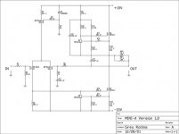
The pcb,s I used are Brian gt. on schema are Q6 enQ7 not used.
With regards Marcus
The pcb,s I used are Brian gt. on schema are Q6 enQ7 not used.
With regards Marcus
An externally hosted image should be here but it was not working when we last tested it.
I cannot read your schematic for part numbers, but if you reduce the value of the emitter resistors the bias current will increase. You should have approximately .5V over the emitter resistors, so you can calculate the bias per FET. Watch the junction temperatures.
Adding additional FETs is another alternative - use the same emitter resistors as the rest. You'll be a bit safer using more output devices if you are looking for a large increase, since thermal issues will be reduced.
Adding additional FETs is another alternative - use the same emitter resistors as the rest. You'll be a bit safer using more output devices if you are looking for a large increase, since thermal issues will be reduced.
Change the resistor from the base of ccs bjt thath`s connected to it`s colector bootstrap load. Higher value gives a higher ccs bias, but look out for ccs modulation ratio it will be changed so you must change the modulation resistor to...
I still think that simply altering the emitter and current sense resistors (R18, R19, R20, R21 on Zen Mod's scematic) is a simpler way to change the bias without altering the AC current gain.
Ignoring the active portion of the CCS for the moment (mentally remove R11), R18 sets the current in the CCS. The base of Q4 will be .6V above its emitter. The voltage at the junction of R15/R18 and Q6 drain will also be .6 V, and the emitter resistor sets the current.
In this circuit the reduced a bit due to the current in R15, a result of the R11 connection. In practice, it ends up around .5V. Reduce the value of R18 and the current must increase. At 0R33 you'll get ~1.6A per output device. The AC current gain is unaffected if you replace R20 and R21 with the same value as you choose for R18 and R19.
Edit: Bogdan's suggestion is good for small changes in bias. It should not affect the AC current gain, which is set by the ratios of R15/R12 and R18/R20//R21.
hello
thanks for the help , but so many numbers of resistors now named, that I all ready not now how en what
to do.
I try to make a beter readable schematic , but Its impossebel.
mabe to morrow I manege. I can send it very clear by email but were do I send it.
sorry for my poor English
regards Marcus
thanks for the help , but so many numbers of resistors now named, that I all ready not now how en what
to do.
I try to make a beter readable schematic , but Its impossebel.
mabe to morrow I manege. I can send it very clear by email but were do I send it.
sorry for my poor English
regards Marcus
BrianGT's schematic and the one posted above are essentially the same schematic with exception that the input section is slightly different. Just compare the above and its resistor numbers and placement with your original schematic. Not hard, just a little time consuming.
Hi Marcus,
Just lay the Zen Mod posted schematic next to yours and relabel the output stage with the mini aleph numbers. The A30 has more output stage resistors, but the other ACSs and outputs are just parallels of the single.
Or a simple way - you state 1.2A bias - is that per FET? What is your bias goal? We can figure out resistor values for you. Drop all the 5W resistors to 0R33 for 1.6A per output FET. So, if you use a 3 output/3 ACS output stage you'll be at ~4.8A total bias. That should give you about 30 W into 8R. but be a bit toasty, at 35 Watts per FET. Unless your sinks are huge, you'll fry.
Need more current? If you go to 0R22, for 7.5A total for 3 pairs of outputs. You'll fry your FETS, so you'll need to add more outputs, which is really the best idea all around. If you're at 1.2A/fet and 22 V rails you're right at the recommended max load per FET.
So, the short answer is: if you need more current, add more output FETs. For each output or ACS fet you add, add one more resistor to the current sense batch (R20//R21, etc.).
Again, watch the dissipation on higher bias. Your heat sinks will need to be able to 300 W at 30C rise, or .1deg/W - pretty big.
hello
I have changed the resistors on the transistorboards original they 1 ohm en I changed it in 0,47 ohm. in total 12 resistors.
now the Aleph take s 1 amp 230 v from the net. en 5 amp each site total. 22,5 V
thanks very much for helping, and keep up the good work.
regards Marcus
I have changed the resistors on the transistorboards original they 1 ohm en I changed it in 0,47 ohm. in total 12 resistors.
now the Aleph take s 1 amp 230 v from the net. en 5 amp each site total. 22,5 V
thanks very much for helping, and keep up the good work.
regards Marcus
- Status
- Not open for further replies.
- Home
- Amplifiers
- Pass Labs
- Aleph30 higher bias