Hi Everyone,
I have assembled PCB for Aleph2, just waiting to mount them and have some questions.
1. Aleph PSU is 57V, after going through similar threads what I have understood is that no modification is required to circuit for 57V rails. If someone can confirm, that would be confidence boosting.
2. Can I mount 12 O/P Devices of Aleph2 on one heatsink 600 X 300 X 84
Therm. Resistance (°C/W) @ Length 200mm - 0.08
Ambient Temp : 35 C
3. What if I want to decrease the bias a bit as I need 100W per channel. Will lowering bias have any impact on sound quality.
4. To decrease bias i need to use a pot in place of R19 in original schematic ?
5. Do I need to match MOSFET for Aleph2?
Last edited:
The 12 big mosfets are used in two groups of 6 in parallel. So the mosfets within each group need to be matched.
What's your transformer AC voltages and VA rating? Is your +/-57V without a load?
What's your transformer AC voltages and VA rating? Is your +/-57V without a load?
Thank you Dennis
Its a 1200VA with 4 pair of secondaries.
800VA 40V - For Aleph2
400VA 30V - For F5T
Yes, 57V is without load.
Its a 1200VA with 4 pair of secondaries.
800VA 40V - For Aleph2
400VA 30V - For F5T
Yes, 57V is without load.
Are you looking to run an F5T and A2 from the same power supply? Is that for 1+1 channel of each or 2+2? (That'll be a lot of heat to dissipate.)
Anyway, with 40V secondaries, you're probably looking at around +/-50V-ish loaded. That's somewhat higher than the A2's spec'ed +/-45V rails but manageable. I don't think there's a real need to change anything if your heatsinking and mosfet mounting is up to the task. You might consider losing a bit more voltage in a CRC power supply (by increasing the resistance and be mindful of the resistor dissipation) or even through something more active (say, a cap multiplier).
600mm is a pretty tall/long heatsink and unless you can space the output devices out properly, you won't be taking full advantage of it. Perhaps you can post some photos of the heatsink in question?
Which A2 PCBs are you using and what is the layout/spacing of the power mosfets?
Thank you Dennis for confirming that no modification is needed.
Its 1 + 1, One channel of each F5T and Aleph2.
Aleph is using CCLCC
I wanted to experience both F5T and Aleph2. Then I'll decide which one to keep or both and biamp.
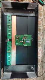
This is what I am going to try for PCB placement.
Its 1 + 1, One channel of each F5T and Aleph2.
Aleph is using CCLCC
I wanted to experience both F5T and Aleph2. Then I'll decide which one to keep or both and biamp.
This is what I am going to try for PCB placement.
Attachments
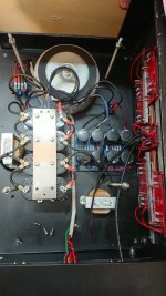

Aleph2 one channel assembled. Did a quick test.
Rail voltage 55V
Voltage measured across one source resistor, settled around 334mV
DC Offset : Started with 2.5 V on startup and down to 30mV in 15 seconds and settled around -11mV.
Is this normal?
Rail voltage 55V
Voltage measured across one source resistor, settled around 334mV
DC Offset : Started with 2.5 V on startup and down to 30mV in 15 seconds and settled around -11mV.
Is this normal?
Attachments
Low bias on Aleph2
Hi Everyone,
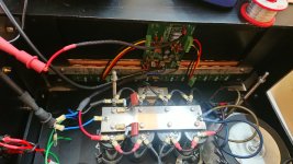
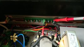
I am getting low bias on Aleph2
PSU with load - 50V
After using trimpot at R19, at around 186K the voltage measured across each resistor(1ohm) is different between range 0.460mV to 0.520mV, DC offset at output is under 10mV.
Observation : The first from left in picture IRFP9610 is hotter compared to other two.
Music is loooooovelyyyyyyyy. 🙂
1. Is this variation normal?
2. To what value I can increase R19 to increase bias without any other change in circuit and with heat taken care of.
3. What could be the reason of low bias even after increasing R19 to 186K.
Thank you
Hi Everyone,
I am getting low bias on Aleph2
PSU with load - 50V
After using trimpot at R19, at around 186K the voltage measured across each resistor(1ohm) is different between range 0.460mV to 0.520mV, DC offset at output is under 10mV.
Observation : The first from left in picture IRFP9610 is hotter compared to other two.
Music is loooooovelyyyyyyyy. 🙂
1. Is this variation normal?
2. To what value I can increase R19 to increase bias without any other change in circuit and with heat taken care of.
3. What could be the reason of low bias even after increasing R19 to 186K.
Thank you
Attachments
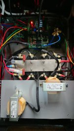
I do not know the board and did not check the foto's, but check the schematic in the service manual. The top 9610 is the constant current source (about 20mA according to the service manual). The other two are the input differential pair (which need to be matched). They are sharing the current (about 10mA each).
I assume it is the top one that is hotter?
I assume it is the top one that is hotter?
1. Variation measured could be due to mismatching of fets OR resistors.
Assuming the fets are properly matched, check the value of each resistor with a good low-Ohm meter. Are they equal? If not, what variation?
2. Assuming you are using normal values elsewhere, 186k seems very high. Check the Aleph 2 doc attached to the first post in https://www.diyaudio.com/community/...or-modern-ums-chassis-builders-thread.382316/ to see examples of values with the bias they will give.
3. Assuming you have 6 fets, the total bias in A is equal to the TOTAL drop in V across ALL 6 1R resistors. If you have about 500mV drop across each 1R resistor, then 6 x 0.5 = 3A, which is the design spec.
You can also use a clamp meter on psu rail wires.
I would advise to:
A. Check 1R resistor values
B. If the resistors are the same, check fet matching
C. Go back to original bias resistor values to see if everything functions normally, before changing things.
Correct, Q3.I do not know the board and did not check the foto's, but check the schematic in the service manual. The top 9610 is the constant current source (about 20mA according to the service manual). The other two are the input differential pair (which need to be matched). They are sharing the current (about 10mA each).
I assume it is the top one that is hotter?
Thank you for explanation.
Hello Everyone,
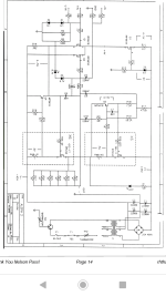
Board BrianGT, original Aleph schematic. I have compared values visually between board and schematic for each component, except C6, C7 and C8.
50VDC with load.
Sharing some measurements.
Across R11 5.3V
Across R14 4.3V
Across Z5 9V
Between Collector-Emitter MPSA18 4.2 V
R19 is around 56K
Across 1Ohm resistor around 300mV, have to increase R19 to 186K to reach 500mV
I am using RN65D except for 1 Ohm and 0.47 Ohm Metal oxide 5%
Wondering why I am short of 0.2V to touch the 0.5V mark across 1Ohm.
If there is a sure way to know where the problem is, I can take those components out and measure those values.
Last edited:
1K trimpot connected as variable resistor in place of R14
preset to 400R, there you set output DC offset
R19 - replace with 100K fixed resistor in series with 100K trimpot connected as variable resistor - that's for Iq setting
preset to 400R, there you set output DC offset
R19 - replace with 100K fixed resistor in series with 100K trimpot connected as variable resistor - that's for Iq setting
Thankyou Zen
I already have a 200K trimpot at R19
Will install on R14 as well.
Problem is bias is low in a range around 300mV if R19 is 56K, as per schematic it should be 500mV.
If I raise R19 to 186K then only it reaches 500mV.
I already have a 200K trimpot at R19
Will install on R14 as well.
Problem is bias is low in a range around 300mV if R19 is 56K, as per schematic it should be 500mV.
If I raise R19 to 186K then only it reaches 500mV.
I can't see a problem, that adjust is normal procedure
you're good then, if DC Offset is good too
you're good then, if DC Offset is good too
If that is Q3, that is normal. Q1 and Q2 should be around the same temp.Observation : The first from left in picture IRFP9610 is hotter compared to other two
You should be cooking pretty good at 500mv. Especially if your ambiant temp is 35C or 95F. Are you using 1 ohm source resistors?If I raise R19 to 186K then only it reaches 500mV.
Thank you Zen for confirming.I can't see a problem, that adjust is normal procedure
you're good then, if DC Offset is good too
DC offset is good, 10mV
So can I go higher than 200K with R19, more bias?
try and see
max possible Iq, with parts used, is when R19 is open (not installed)
roughly 0V6 across source resistors
DC Offset will tell (if it goes positive) do you need to alter R14 position
max possible Iq, with parts used, is when R19 is open (not installed)
roughly 0V6 across source resistors
DC Offset will tell (if it goes positive) do you need to alter R14 position
- Home
- Amplifiers
- Pass Labs
- Aleph2 60V PSU and Heatsink