Did some measurements- biased the current, aim 0.5V as per Eric website.
I was able to achieve relative offset easily to a few milivolts. The main problem is the absolute dc offsets. It drifts like crazy and thermal dependent . I noticed with this particular board there is no pad for the offset resistor r1/4 and 44/45 as per schematics. A few solutions has been mentioned either to lower the Mcmillan resistors but it seems the easiest is to short outputs to ground. The values of the resistors are not important as per document but now i have to work out the way to connect the resistors. The differential dc offset protection circuit keeping turn itself on/off depending on the values of the absolute offset is so annoying😕😕
I was able to achieve relative offset easily to a few milivolts. The main problem is the absolute dc offsets. It drifts like crazy and thermal dependent . I noticed with this particular board there is no pad for the offset resistor r1/4 and 44/45 as per schematics. A few solutions has been mentioned either to lower the Mcmillan resistors but it seems the easiest is to short outputs to ground. The values of the resistors are not important as per document but now i have to work out the way to connect the resistors. The differential dc offset protection circuit keeping turn itself on/off depending on the values of the absolute offset is so annoying😕😕
Hi guys, i am looking for some help. I have solder in resistors from output to ground. Now the problem seems to be in reverse. Prior to having those output resistors to ground i am unable to settle abs dc offset but the rel offset is manageable. But once the output resistors are short to ground now the abs dc offset is low +/-30mV but the relative dc is drifting like crazy even after 1 hour from +1/-1V. The differential dc offset protection circuit is flicking on/off like crazy even on low rel dc offset of 200mV. I have no idea how to adjust the pots on the protection board to adjust the upper limit of the off sets. 😕😕😕
Hi,
what values did you use for R1/4/44/45? The original schematic uses 62R which would be a good value to start with.
Like ZEN Mod said, start without the protection circuit.
How can you set the relative offset? normally it is determined mainly by the input diff pair and more or less fixed. Where do you measure?
William
Thank you for the responses guys. I measured the rel offset at directly speaker output on the pcb btw positive and negative outputs. The absolute offset was measured btw positive output and ground . I adjust the bias current the V1 and V3 and it measures 480mV,485mV both chanels but does drift . I connect outputs to ground using 50R 2W and 70R 5W parallel to each other ( i don't have any 62R and i thought as per diy wiki that the value is not important ranging from 20R to 100R).
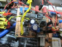
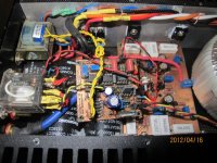
As stated i bought these amps off another diyer. All i can make from it that written on the board that it is a differential dc protection circuit and push on power button but the the rest of the writing on the board is all smudge, The are 3 pots on the protection board but i can 't see which pots does what and how to initiate or reset the board. I can see the board was design by Daniel Purvis?.
As stated i bought these amps off another diyer. All i can make from it that written on the board that it is a differential dc protection circuit and push on power button but the the rest of the writing on the board is all smudge, The are 3 pots on the protection board but i can 't see which pots does what and how to initiate or reset the board. I can see the board was design by Daniel Purvis?.
Attachments
Last edited:
Ok ,check again today
one of the monoblock is working fine, biased at 500mV both chanels, relative dc offset is 35mV, absolute dc offset is 200mV and i did not use output resistors to ground. The other monoblock seem to be having problem biased at same level ie 480/500mV, but dc offset (relative) drift up to 8V within few minutes but absolute dc offset is about 1V. When i adjust the v2 pot for absolute offset to get to close to 10mV the relative dc offset was lower down to 20mV but rapidly climbing up to 8V soon.
Checking voltages across 392ohm resistors measures about 4.0v and 4.2 V but i accidentally shorted the 2 resistors. Please advise where should i check next?
Thank you for your help in advance.
Quan
- Status
- Not open for further replies.